Quantcast
Channel: Servers – Noise
Viewing all 614 articles
Browse latest View live

Storage Pod 6.0: Building a 60 Drive 480TB Storage Server

$
0
0

Post Syndicated from Andy Klein original https://www.backblaze.com/blog/open-source-data-storage-server/

Storage Pod 6.0
Storage Pod 6.0 deploys 60 off-the-shelf hard drives in a 4U chassis to lower the cost of our latest data storage server to just $0.036/GB. That’s 22 percent less than our Storage Pod 5.0 storage server that used 45 drives to store data for $0.044/GB. The Storage Pod 6.0 hardware design is, as always, open source so we’ve included the blueprints, STEP files, wiring diagrams, build instructions and a parts list so you can build your very own Storage Pod. Your cost may be a bit more, but it is possible for you to build a 4U server with 480TB of data storage for less than a nickel ($0.05) a gigabyte – read on.

A little Storage Pod history

In 2009, Storage Pod 1.0 changed the landscape in data storage servers by delivering 67.5TB of storage in a 4U box for just $0.11/GB – that was up to 10 times lower than comparable systems on the market at the time. We also open-sourced the hardware design of Storage Pod 1.0 and companies, universities, and even weekend hobbyist started building their own Storage Pods.

Over the years we introduced updates to the Storage Pod design, driving down the cost while improving the reliability and durability with each iteration. Storage Pod 5.0 marked our initial use of the Agile manufacturing and design methodology which helped identify and squeeze out more costs, driving our cost per GB of storage below $0.05. Agile also enabled us to manage a rapid design prototyping process that allowed us stretch the Storage Pod chassis to include 60 drives then produce 2-D and 3-D specifications, a build book, a bill of materials and update our manufacturing and assembly processes for the new design – Storage Pod 6.0. All of this in about 6 months.

What’s new in Storage Pod 6.0

60 drive storage server

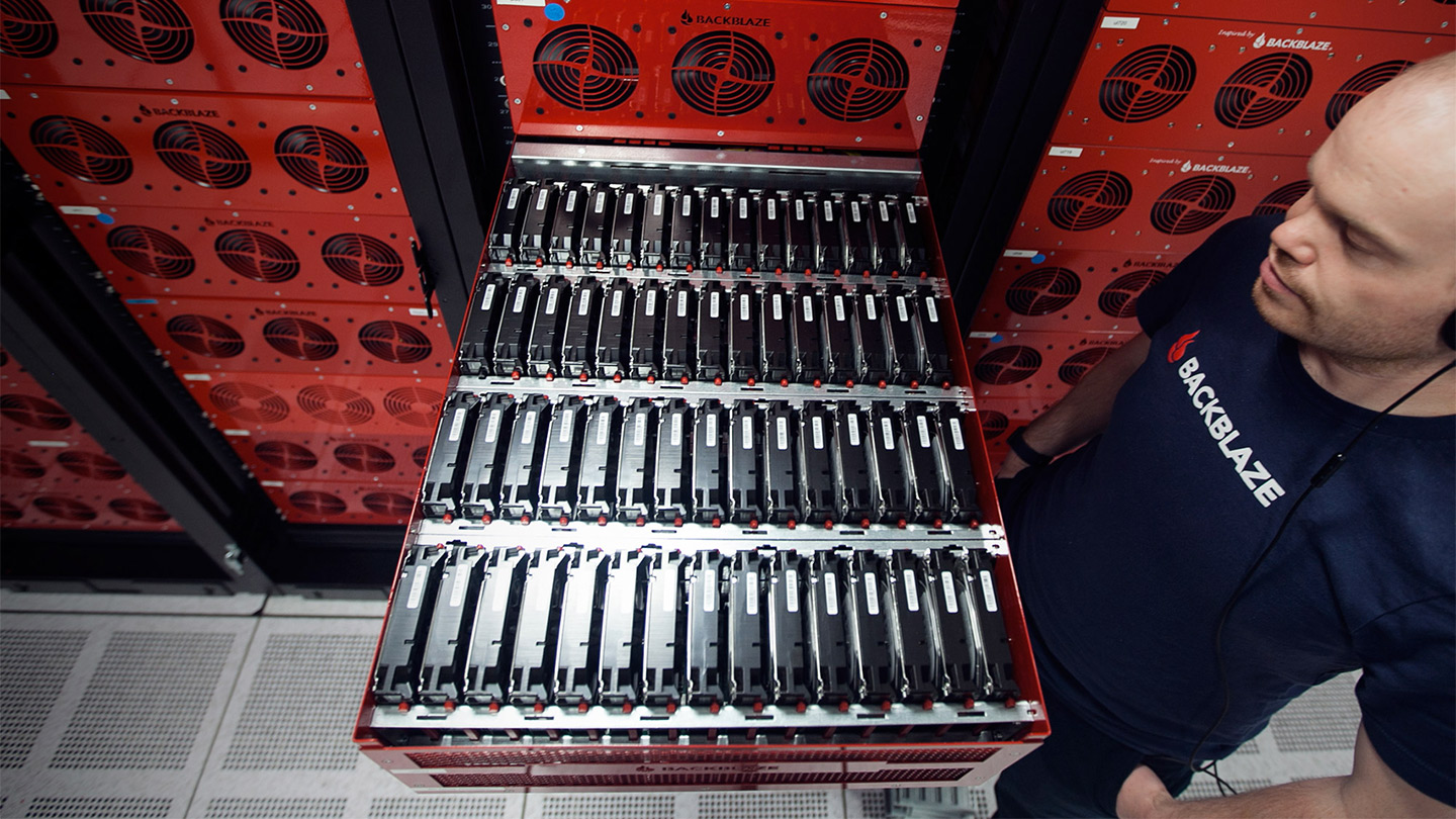
What’s new is 60 drives in a 4U chassis. That’s a 33 percent increase to the storage density in the same rack space. Using 4TB drives in a 60-drive Storage Pod increases the amount of storage in a standard 40U rack from 1.8 to 2.4 Petabytes. Of course, by using 8TB drives you’d get a 480TB data storage server in 4U server and 4.8 Petabytes in a standard rack.

When looking at what’s new in Storage Pod 6.0 it would easy to say it has 60 drives and stop there. After all, the Motherboard, CPU, memory, SATA cards, and backplanes we use didn’t change from 5.0. But expanding to 60 drives created all kinds of things to consider, for example:

  • How long do you make the chassis before it is too long for the rack?
  • Will we need more cooling?
  • Will the power supplies need to be upgraded?
  • Will the SATA cables be too long? The maximum spec’d length is 1 meter.
  • Can the SATA cards keep up with the 15 more drives? Or will we need to upgrade them?
  • Will the CPU and the motherboard be able to handle the additional data load of 15 more drives?
  • Will more or faster memory be required?
  • Will the overall Storage Pod be correctly balanced between CPU, memory, storage and other components so that nothing is over/under-spec’ed?
  • What hard drives will work with this configuration? Would we have to use enterprise drives? Just kidding!

Rapidly iterating to the right design

As part of the prototyping effort we built multiple configurations and Backblaze Labs put each configuration through its paces. To do this we assembled a Backblaze Vault with 20 prototype Storage Pods in three different configurations. Since each Storage Pod in a Backblaze Vault is expected to perform similarly, we monitored and detected those Storage Pods that were lagging as well as those that were “bored”. By doing this were were able to determine that most of the components in Storage Pod 6.0 did not need to be upgraded to achieve optimal performanace in Backblaze Vaults utlizing 60 drive Storage Pods.

We did make some changes to Storage Pod 6.0 however:

  • Increased the chassis by 5 ½” from 28 1/16” to 33 9/16” in length. Server racks are typically 29” in depth, more on that later.
  • Increased the length of the backplane tray to support 12 backplanes.
  • Added 1 additional drive bracket to handle another row of 15 drives.
  • Added 3 more backplanes and 1 more SATA card.
  • Added 3 more SATA cables.
  • Changed the routing to of the SATA-3 cables to stay within the 1-meter length spec.
  • Updated the pigtail cable design so we could power the three additional backplanes.
  • Changed the routing of the power cables on the backplane tray.
  • Changed the on/off switch retiring the ele-302 and replacing it with the Chill-22.
  • Increased the length of the lid over the drive bay 22 7/8”.

That last item, increasing the length of the drive bay lid, led to a redesign of both lids. Why?

Lids and Tabs

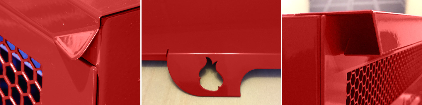
The lid from Storage Pod 5.0 (on the left above) proved to be difficult to remove when it was stretched another 4+ inches. The tabs didn’t provide enough leverage to easily open the longer drive lid. As a consequence Storage Pod 6.0 has a new design (shown on the right above) which provides much better leverage. The design in the middle was one of the prototype designs we tried, but in the end the “flame” kept catching the fingers of the ops folks when they opened or closed the lid.

Too long for the server rack?

The 6.0 chassis is 33 9/16” in length and 35 1/16” with the lids on. A rack is typically 29” in depth, leaving 4+ inches of Storage Pod chassis “hanging out.” We decided to keep the front (Backblaze logo side) aligned to the front of the rack and let the excess hang off the back in the warm aisle of the datacenter. A majority of a pod’s weight is in the front (60 drives!) so the rails support this weight. The overhang is on the back side of the rack, but there’s plenty of room between the rows of racks, so there’s no issue with space. We’re pointing out the overhang so if you end up building your own Storage Pod 6.0 server, you’ll leave enough space behind, or in front, of your rack for the overhang.

The cost in dollars

There are actually three different prices for a Storage Pod. Below are the costs of each of these scenarios to build a 180TB Storage Pod 6.0 storage server with 4TB hard drives:

How Built Total Cost Description
Backblaze $8,733.73 The cost for Backblaze given that we purchase 500+ Storage Pods and 20,000+ hard drives per year. This includes materials, assembly, and testing.
You Build It $10,398.57 The cost for you to build one Storage Pod 6.0 server by buying the parts and assembling it yourself.
You Buy It $12,849.40 The cost for you to purchase one already assembled Storage Pod 6.0 server from a third-party supplier and then purchase and install 4TB hard drives yourself.
These prices do not include packaging, shipping, taxes, VAT, etc.

Since we increased the number of drives from 45 to 60, comparing the total cost of Storage Pod 6.0 to previous the 45-drive versions isn’t appropriate. Instead we can compare them using the “Cost per GB” of storage.

The Cost per GB of storage

Using the Backblaze cost for comparison, below is the Cost per GB of building the different Storage Pod versions.

Storage Pod version

As you can see in the table, the cost in actual dollars increased by $760 with Storage Pod 6.0, but the Cost per GB decreased nearly a penny ($0.008) given the increased number of drives and some chassis design optimizations.

Saving $0.008 per GB may not seem very innovative, but think about what happens when that trivial amount is multiplied across the hundreds of Petabytes of data our B2 Cloud Storage service will store over the coming months and years. A little innovation goes a long way.

Building your own Storage Pod 6.0 server

You can build your own Storage Pod. Here’s what you need to get started:

Chassis – We’ve provided all the drawings you should need to build (or to have built) your own chassis. We’ve had multiple metal bending shops use these files to make a Storage Pod chassis. You get to pick the color.

Parts – In Appendix A we’ve listed all the parts you’ll need for a Storage Pod. Most of the parts can be purchased online via Amazon, Newegg, etc. As noted on the parts list, some parts are purchased either through a distributor or from the contract assemblers.

Wiring – You can purchase the power wiring harness and pigtails as noted on the parts list, but you can also build your own. Whether you build or buy, you’ll want to download the instructions on how to route the cables in the backplane tray.

Build Book – Once you’ve gathered all the parts, you’ll need the Build Book for step-by-step assembly instructions.

As a reminder, Backblaze does not sell Storage Pods, and the design is open source, so we don’t provide support or warranty for people who choose to build their own Storage Pod. That said, if you do build your own, we’d like to hear from you.

Building a 480TB Storage Pod for less than a $0.05 per GB

We’ve used 4TB drives in this post for consistency, but we have in fact built Storage Pods with 5-, 6- and even 8-TB drives. If you are building a Storage Pod 6.0 storage server, you can certainly use higher capacity drives. To make it easy, the chart below is your estimated cost if you were to build your own Storage Pod using the drives noted. We used the lowest “Street Price” from Amazon or Newegg for the price of the 60 hard drives. The list is sorted by the Cost per GB (lowest to highest). The (*) indicates we use this drive model in our datacenter.
Storage Pod Cost per GB
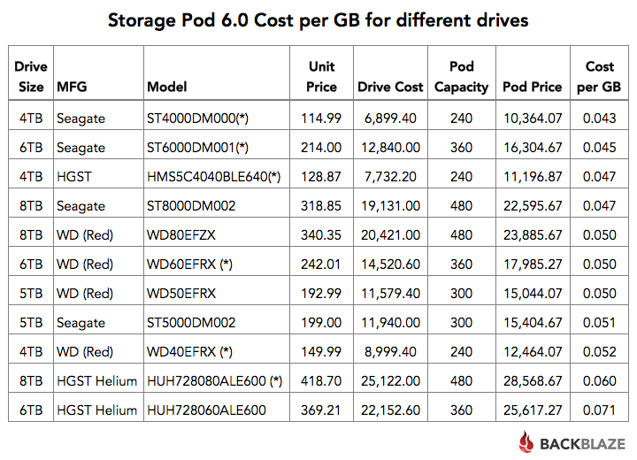
As you can see there are multiple drive models and capacities you can use to achieve a Cost per GB of $0.05 or less. Of course we aren’t counting your sweat-equity in building a Storage Pod, nor do we include the software you are planning to run. If you are looking for capacity, think about using the Seagate 8TB drives to get nearly a half a petabyte of storage in a 4U footprint (albeit with a 4” overhang) for just $0.047 a GB. Total cost: $22,600.

What about SMR drives?

Depending on your particular needs, you might consider using SMR hard drives. An SMR drive stores data more densely on each disk platter surface by “overlapping” tracks of data. This lowers the cost to store data. The downside is that when data is deleted, the newly freed space can be extremely slow to reuse. As such SMR drives are generally used for archiving duties where data is written sequentially to a drive with few, and preferably no, deletions. If this type of capability fits your application, you will find SMR hard drives to very inexpensive. For example, a Seagate 8TB Archive drive (model: ST8000AS0002) is $214.99, making the total cost for a 480TB Storage Pod 6.0 storage server only $16,364.07 or a very impressive $0.034 per GB. By the way, if you’re looking for off-site data archive storage, Backblaze B2 will store your data for just $0.005/GB/month.

Buying a Storage Pod

Backblaze does not sell Storage Pods or parts. If you are interested in buying a Storage Pod 6.0 storage server (without drives), you can check out the folks at Backuppods. They have partnered with Evolve Manufacturing to deliver Backblaze-inspired Storage Pods. Evolve Manufacturing is the contract manufacturer used by Backblaze to manufacture and assemble Storage Pod versions 4.5, 5.0 and now 6.0. Backuppods.com offers a fully assembled and tested Storage Pod 6.0 server (less drives) for $5,950.00 plus shipping, handling and tax. They also sell older Storage Pod versions. Please check out their website for the models and configurations they are currently offering.

Appendix A: Storage Pod 6.0 Parts List

Below is the list of parts you’ll need to build your own Storage Pod 6.0. The prices listed are “street” prices. You should be able to find these items online or from the manufacturer in quantities sufficient to build one Storage Pod. Good luck and happy building.

Item
Qty
Price
Total
Notes
4U Custom Chassis
Includes case, supports, trays, etc.
1
$995.00
$995.00
1
Power Supply
EVGA Supernova NEX750G
2
$119.90
$239.98
On/Off Switch & Cable
Primochill 120-G1-0750-XR (Chill-22)
1
$14.95
$14.95
Case Fan
FAN AXIAL 120X25MM VAPO 12VDC
3
$10.60
$31.80
Dampener Kits
Power Supply Vibration Dampener
2
$4.45
$8.90
Soft Fan Mount
AFM03B (2 tab ends)
12
$0.42
$4.99
Motherboard
Supermicro MBD-X9SRH-7TF-O (MicroATX)
1
$539.50
$539.50
CPU Fan
DYNATRON R13 1U Server CPU FAN
1
$45.71
$45.71
CPU
Intel XEON E5 -1620 V2 (Quad Core)
1
$343.94
$343.94
8GB RAM
PC3-12800 DDR3-1600MHz 240-Pin
4
$89.49
$357.96
Port Multiplier Backplanes
5 Port Backplane (Marvell 9715 chipset)
12
$45.68
$548.10
2, 1
SATA III Card
4-post PCIe Express (Marvell 9235 chipset)
3
$57.10
$171.30
2, 1
SATA III Cable
SATA cables RA-to-STR 1M locking
12
$3.33
$39.90
3, 1
Cable Harness – PSU1
24-pin – Backblaze to Pigtail
1
$33.00
$33.00
1
Cable Harness – PSU2
20-pin – Backblaze to Pigtail
1
$31.84
$31.84
1
Cable Pigtail
24-pin – EVGA NEX750G Connector
2
$16.43
$16.43
1
Screw: 6-32 X 1/4 Phillips PAN ZPS
12
$0.015
$1.83
4
Screw: 4-40 X 5/16 Phillips PAN ZPS ROHS
60
$0.015
$1.20
4
Screw: 6-32 X 1/4 Phillips 100D Flat ZPS
39
$0.20
$7.76
4
Screw: M3 X 5MM Long Phillips, HD
4
$0.95
$3.81
Standoff: M3 X 5MM Long Hex, SS
4
$0.69
$2.74
Foam strip for fan plate – 1/2″ x 17″ x 3/4″
1
$0.55
$0.55
Cable Tie, 8.3″ x 0.225″
4
$0.25
$1.00
Cable Tie, 4″ length
2
$0.03
$0.06
Plastic Drive Guides
120
$0.25
$30.00
1
Label,Serial-Model,Transducer, Blnk
30
$0.20
$6.00
Total
$3,494.67

NOTES:

  • May be able to be purchased from backuppods.com, price may vary.
  • Sunrich and CFI make the recommended backplanes and Sunrich and Syba make the recommended SATA Cards.
  • Nippon Labs makes the recommended SATA cables, but others may work.
  • Sold in packages of 100, used 100 package price for Extended Cost.


The post Storage Pod 6.0: Building a 60 Drive 480TB Storage Server appeared first on Backblaze Blog | The Life of a Cloud Backup Company.


AWS CodeDeploy Deployments with HashiCorp Consul

$
0
0

Post Syndicated from George Huang original http://blogs.aws.amazon.com/application-management/post/Tx1MURIM5X45IKX/AWS-CodeDeploy-Deployments-with-HashiCorp-Consul

Learn how to use AWS CodeDeploy and HashiCorp Consul together for your application deployments. 

AWS CodeDeploy automates code deployments to Amazon Elastic Compute Cloud (Amazon EC2) and on-premises servers. HashiCorp Consul is an open-source tool providing service discovery and orchestration for modern applications. 

Learn how to get started by visiting the guest post on the AWS Partner Network Blog. You can see a full list of CodeDeploy product integrations by visiting here

Surviving the Zombie Apocalypse with Serverless Microservices

$
0
0

Post Syndicated from Aaron Kao original https://aws.amazon.com/blogs/compute/surviving-the-zombie-apocalypse-with-serverless-microservices/

Run Apps without the Bite!

by: Kyle Somers – Associate Solutions Architect

Let’s face it, managing servers is a pain! Capacity management and scaling is even worse. Now imagine dedicating your time to SysOps during a zombie apocalypse — barricading the door from flesh eaters with one arm while patching an OS with the other.

This sounds like something straight out of a nightmare. Lucky for you, this doesn’t have to be the case. Over at AWS, we’re making it easier than ever to build and power apps at scale with powerful managed services, so you can focus on your core business – like surviving – while we handle the infrastructure management that helps you do so.

Join the AWS Lambda Signal Corps!

At AWS re:Invent in 2015, we piloted a workshop where participants worked in groups to build a serverless chat application for zombie apocalypse survivors, using Amazon S3, Amazon DynamoDB, Amazon API Gateway, and AWS Lambda. Participants learned about microservices design patterns and best practices. They then extended the functionality of the serverless chat application with various add-on functionalities – such as mobile SMS integration, and zombie motion detection – using additional services like Amazon SNS and Amazon Elasticsearch Service.

Between the widespread interest in serverless architectures and AWS Lambda by our customers, we’ve recognized the excitement around this subject. Therefore, we are happy to announce that we’ll be taking this event on the road in the U.S. and abroad to recruit new developers for the AWS Lambda Signal Corps!


Help us save humanity! Learn More and Register Here!


Washington, DC | March 10 – Mission Accomplished!

San Francisco, CA @ AWS Loft | March 24 – Mission Accomplished!

New York City, NY @ AWS Loft | April 13 – Mission Accomplished!

London, England @ AWS Loft | April 25

Austin, TX | April 26

Atlanta, GA | May 4

Santa Monica, CA | June 7

Berlin, Germany | July 19

San Francisco, CA @ AWS Loft | August 16

New York City, NY @ AWS Loft | August 18


If you’re unable to join us at one of these workshops, that’s OK! In this post, I’ll show you how our survivor chat application incorporates some important microservices design patterns and how you can power your apps in the same way using a serverless architecture.


What Are Serverless Architectures?

At AWS, we know that infrastructure management can be challenging. We also understand that customers prefer to focus on delivering value to their business and customers. There’s a lot of undifferentiated heavy lifting to be building and running applications, such as installing software, managing servers, coordinating patch schedules, and scaling to meet demand. Serverless architectures allow you to build and run applications and services without having to manage infrastructure. Your application still runs on servers, but all the server management is done for you by AWS. Serverless architectures can make it easier to build, manage, and scale applications in the cloud by eliminating much of the heavy lifting involved with server management.

Key Benefits of Serverless Architectures

  • No Servers to Manage: There are no servers for you to provision and manage. All the server management is done for you by AWS.
  • Increased Productivity: You can now fully focus your attention on building new features and apps because you are freed from the complexities of server management, allowing you to iterate faster and reduce your development time.
  • Continuous Scaling: Your applications and services automatically scale up and down based on size of the workload.

What Should I Expect to Learn at a Zombie Microservices Workshop?

The workshop content we developed is designed to demonstrate best practices for serverless architectures using AWS. In this post we’ll discuss the following topics:

  • Which services are useful when designing a serverless application on AWS (see below!)
  • Design considerations for messaging, data transformation, and business or app-tier logic when building serverless microservices.
  • Best practices demonstrated in the design of our zombie survivor chat application.
  • Next steps for you to get started building your own serverless microservices!

Several AWS services were used to design our zombie survivor chat application. Each of these services are managed and highly scalable. Let’s take a quick at look at which ones we incorporated in the architecture:

  • AWS Lambda allows you to run your code without provisioning or managing servers. Just upload your code (currently Node.js, Python, or Java) and Lambda takes care of everything required to run and scale your code with high availability. You can set up your code to automatically trigger from other AWS services or call it directly from any web or mobile app. Lambda is used to power many use cases, such as application back ends, scheduled administrative tasks, and even big data workloads via integration with other AWS services such as Amazon S3, DynamoDB, Redshift, and Kinesis.
  • Amazon Simple Storage Service (Amazon S3) is our object storage service, which provides developers and IT teams with secure, durable, and scalable storage in the cloud. S3 is used to support a wide variety of use cases and is easy to use with a simple interface for storing and retrieving any amount of data. In the case of our survivor chat application, it can even be used to host static websites with CORS and DNS support.
  • Amazon API Gateway makes it easy to build RESTful APIs for your applications. API Gateway is scalable and simple to set up, allowing you to build integrations with back-end applications, including code running on AWS Lambda, while the service handles the scaling of your API requests.
  • Amazon DynamoDB is a fast and flexible NoSQL database service for all applications that need consistent, single-digit millisecond latency at any scale. It is a fully managed cloud database and supports both document and key-value store models. Its flexible data model and reliable performance make it a great fit for mobile, web, gaming, ad tech, IoT, and many other applications.

Overview of the Zombie Survivor Chat App

The survivor chat application represents a completely serverless architecture that delivers a baseline chat application (written using AngularJS) to workshop participants upon which additional functionality can be added. In order to deliver this baseline chat application, an AWS CloudFormation template is provided to participants, which spins up the environment in their account. The following diagram represents a high level architecture of the components that are launched automatically:

High-Level Architecture of Survivor Serverless Chat App

  • Amazon S3 bucket is created to store the static web app contents of the chat application.
  • AWS Lambda functions are created to serve as the back-end business logic tier for processing reads/writes of chat messages.
  • API endpoints are created using API Gateway and mapped to Lambda functions. The API Gateway POST method points to a WriteMessages Lambda function. The GET method points to a GetMessages Lambda function.
  • A DynamoDB messages table is provisioned to act as our data store for the messages from the chat application.

Serverless Survivor Chat App Hosted on Amazon S3

With the CloudFormation stack launched and the components built out, the end result is a fully functioning chat app hosted in S3, using API Gateway and Lambda to process requests, and DynamoDB as the persistence for our chat messages.

With this baseline app, participants join in teams to build out additional functionality, including the following:

  • Integration of SMS/MMS via Twilio. Send messages to chat from SMS.
  • Motion sensor detection of nearby zombies with Amazon SNS and Intel® Edison and Grove IoT Starter Kit. AWS provides a shared motion sensor for the workshop, and you consume its messages from SNS.
  • Help-me panic button with IoT.
  • Integration with Slack for messaging from another platform.
  • Typing indicator to see which survivors are typing.
  • Serverless analytics of chat messages using Amazon Elasticsearch Service (Amazon ES).
  • Any other functionality participants can think of!

As a part of the workshop, AWS provides guidance for most of these tasks. With these add-ons completed, the architecture of the chat system begins to look quite a bit more sophisticated, as shown below:

Architecture of Survivor Chat with Additional Add-on Functionality

Architectural Tenants of the Serverless Survivor Chat

For the most part, the design patterns you’d see in a traditional server-yes environment you will also find in a serverless environment. No surprises there. With that said, it never hurts to revisit best practices while learning new ones. So let’s review some key patterns we incorporated in our serverless application.

Decoupling Is Paramount

In the survivor chat application, Lambda functions are serving as our tier for business logic. Since users interact with Lambda at the function level, it serves you well to split up logic into separate functions as much as possible so you can scale the logic tier independently from the source and destinations upon which it serves.

As you’ll see in the architecture diagram in the above section, the application has separate Lambda functions for the chat service, the search service, the indicator service, etc. Decoupling is also incorporated through the use of API Gateway, which exposes our back-end logic via a unified RESTful interface. This model allows us to design our back-end logic with potentially different programming languages, systems, or communications channels, while keeping the requesting endpoints unaware of the implementation. Use this pattern and you won’t cry for help when you need to scale, update, add, or remove pieces of your environment.

Separate Your Data Stores

Treat each data store as an isolated application component of the service it supports. One common pitfall when following microservices architectures is to forget about the data layer. By keeping the data stores specific to the service they support, you can better manage the resources needed at the data layer specifically for that service. This is the true value in microservices.

In the survivor chat application, this practice is illustrated with the Activity and Messages DynamoDB tables. The activity indicator service has its own data store (Activity table) while the chat service has its own (Messages). These tables can scale independently along with their respective services. This scenario also represents a good example of statefuless. The implementation of the talking indicator add-on uses DynamoDB via the Activity table to track state information about which users are talking. Remember, many of the benefits of microservices are lost if the components are still all glued together at the data layer in the end, creating a messy common denominator for scaling.

Leverage Data Transformations up the Stack

When designing a service, data transformation and compatibility are big components. How will you handle inputs from many different clients, users, systems for your service? Will you run different flavors of your environment to correspond with different incoming request standards?  Absolutely not!

With API Gateway, data transformation becomes significantly easier through built-in models and mapping templates. With these features you can build data transformation and mapping logic into the API layer for requests and responses. This results in less work for you since API Gateway is a managed service. In the case of our survivor chat app, AWS Lambda and our survivor chat app require JSON while Twilio likes XML for the SMS integration. This type of transformation can be offloaded to API Gateway, leaving you with a cleaner business tier and one less thing to design around!

Use API Gateway as your interface and Lambda as your common backend implementation. API Gateway uses Apache Velocity Template Language (VTL) and JSONPath for transformation logic. Of course, there is a trade-off to be considered, as a lot of transformation logic could be handled in your business-logic tier (Lambda). But, why manage that yourself in application code when you can transparently handle it in a fully managed service through API Gateway? Here are a few things to keep in mind when handling transformations using API Gateway and Lambda:

  • Transform first; then call your common back-end logic.
  • Use API Gateway VTL transformations first when possible.
  • Use Lambda to preprocess data in ways that VTL can’t.

Using API Gateway VTL for Input/Output Data Transformations


Security Through Service Isolation and Least Privilege

As a general recommendation when designing your services, always utilize least privilege and isolate components of your application to provide control over access. In the survivor chat application, a permissions-based model is used via AWS Identity and Access Management (IAM). IAM is integrated in every service on the AWS platform and provides the capability for services and applications to assume roles with strict permission sets to perform their least-privileged access needs. Along with access controls, you should implement audit and access logging to provide the best visibility into your microservices. This is made easy with Amazon CloudWatch Logs and AWS CloudTrail. CloudTrail enables audit capability of API calls made on the platform while CloudWatch Logs enables you to ship custom log data to AWS. Although our implementation of Amazon Elasticsearch in the survivor chat is used for analyzing chat messages, you can easily ship your log data to it and perform analytics on your application. You can incorporate security best practices in the following ways with the survivor chat application:

  • Each Lambda function should have an IAM role to access only the resources it needs. For example, the GetMessages function can read from the Messages table while the WriteMessages function can write to it. But they cannot access the Activities table that is used to track who is typing for the indicator service.
  • Each API Gateway endpoint must have IAM permissions to execute the Lambda function(s) it is tied to. This model ensures that Lambda is only executed from the principle that is allowed to execute it, in this case the API Gateway method that triggers the back end function.
  • DynamoDB requires read/write permissions via IAM, which limits anonymous database activity.
  • Use AWS CloudTrail to audit API activity on the platform and among the various services. This provides traceability, especially to see who is invoking your Lambda functions.
  • Design Lambda functions to publish meaningful outputs, as these are logged to CloudWatch Logs on your behalf.

FYI, in our application, we allow anonymous access to the chat API Gateway endpoints. We want to encourage all survivors to plug into the service without prior registration and start communicating. We’ve assumed zombies aren’t intelligent enough to hack into our communication channels. Until the apocalypse, though, stay true to API keys and authorization with signatures, which API Gateway supports!

Don’t Abandon Dev/Test

When developing with microservices, you can still leverage separate development and test environments as a part of the deployment lifecycle. AWS provides several features to help you continue building apps along the same trajectory as before, including these:

  • Lambda function versioning and aliases: Use these features to version your functions based on the stages of deployment such as development, testing, staging, pre-production, etc. Or perhaps make changes to an existing Lambda function in production without downtime.
  • Lambda service blueprints: Lambda comes with dozens of blueprints to get you started with prewritten code that you can use as a skeleton, or a fully functioning solution, to complete your serverless back end. These include blueprints with hooks into Slack, S3, DynamoDB, and more.
  • API Gateway deployment stages: Similar to Lambda versioning, this feature lets you configure separate API stages, along with unique stage variables and deployment versions within each stage. This allows you to test your API with the same or different back ends while it progresses through changes that you make at the API layer.
  • Mock Integrations with API Gateway: Configure dummy responses that developers can use to test their code while the true implementation of your API is being developed. Mock integrations make it faster to iterate through the API portion of a development lifecycle by streamlining pieces that used to be very sequential/waterfall.

Using Mock Integrations with API Gateway

Stay Tuned for Updates!

Now that you’ve got the necessary best practices to design your microservices, do you have what it takes to fight against the zombie hoard? The serverless options we explored are ready for you to get started with and the survivors are counting on you!

Be sure to keep an eye on the AWS GitHub repo. Although I didn’t cover each component of the survivor chat app in this post, we’ll be deploying this workshop and code soon for you to launch on your own! Keep an eye out for Zombie Workshops coming to your city, or nominate your city for a workshop here.

For more information on how you can get started with serverless architectures on AWS, refer to the following resources:

Whitepaper – AWS Serverless Multi-Tier Architectures

Reference Architectures and Sample Code

*Special thanks to my colleagues Ben Snively, Curtis Bray, Dean Bryen, Warren Santner, and Aaron Kao at AWS. They were instrumental to our team developing the content referenced in this post.

Judge: RIAA and MPAA Can’t Copy Megaupload’s Servers, Yet

$
0
0

Post Syndicated from Ernesto original https://torrentfreak.com/judge-riaa-and-mpaa-cant-copy-megauploads-servers-yet-160427/

megaupload-logoWell over four years have passed since Megaupload was shutdown, but all this time there has been no real progress on the legal front.

Last December a New Zealand District Court judge ruled that Kim Dotcom and his colleagues can be extradited to the United States to face criminal charges, a decision that’s currently under appeal.

With the criminal case pending, the civil lawsuits against the major record labels and Hollywood’s top movie studios have been halted as well.

Fearing that they might influence criminal proceedings, Megaupload’s legal team have had these cases put on hold since 2014, with permission from the copyright holders. However, when Megaupload’s counsel recently opted for another stay, the RIAA and MPAA objected.

Instead of simply signing off on another extension, the movie and music industry groups asked for permission to subpoena Megaupload’s former hosting provider Cogent Communications. Suggesting that the data might not be safe, they asked to make a backup of some crucial evidence the provider has in storage.

“To avoid the risk of substantial prejudice to Plaintiffs from the potential loss of the relevant data in Cogent’s possession, the Court should carve out of any further stay of this case the permission for Plaintiffs to subpoena Cogent for a forensic copy of that data,” both groups informed the court.

The MPAA and RIAA even offered to pay the costs of such a backup, which they estimate to be in the range of $20,000 or less.

Megaupload’s legal team, however, rejected the proposal. Among other things, they argued that privacy sensitive data on their former customers should not be freely shared, and asked the court not to issue a subpoena.

Last Friday both parties presented their case during a hearing and after careful deliberation District Court Judge Liam O’Grady has now decided (pdf) not to issue a subpoena.

ordermegaex

Instead, he decided that things should stay as they are, meaning that Cogent will be the only party that has a copy of the Megaupload data in question. RIAA, MPAA or Megaupload should, however, inform the court if they have concrete evidence that this data is at risk.

“…if any party gains knowledge that any potential evidence in this case, including digital evidence currently being held by Cogent Communications, Inc., is being or might be destroyed, it should notify the Court immediately.”

This decision can be seen as win for Megaupload and Kim Dotcom, as they have successfully averted an attempt from the movie and music companies to gain access to crucial evidence in the case before the official discovery process begins.

“We are pleased that the Federal Court granted the Megaupload defendants’ request for a stay of the civil copyright cases and denied the MPAA and RIAA plaintiffs’ request for early discovery,” Ira Rothken, Megaupload’s Lead Global Counsel, informs TorrentFreak

“The stay will assist the orderly conduct of parallel criminal related proceedings,” he adds.

As requested by Megaupload, Judge O’Grady agreed to put the civil cases on hold for another six months, after the appeal of the New Zealand extradition decision is heard.

Source: TF, for the latest info on copyright, file-sharing, torrent sites and ANONYMOUS VPN services.

Process Encrypted Data in Amazon EMR with Amazon S3 and AWS KMS

$
0
0

Post Syndicated from Russell Nash original https://blogs.aws.amazon.com/bigdata/post/TxBQTAF3X7VLEP/Process-Encrypted-Data-in-Amazon-EMR-with-Amazon-S3-and-AWS-KMS

Russell Nash is a Solutions Architect with AWS.

Amo Abeyaratne, a Big Data consultant with AWS, also contributed to this post.

One of the most powerful features of Amazon EMR is the close integration with Amazon S3 through EMRFS. This allows you to take advantage of many S3 features, including support for S3 client-side and server-side encryption. In a recent release, EMR supported S3 server-side encryption with AWS KMS keys (SSE-KMS), alongside the already supported SSE-S3 (S3 managed keys) and S3 client-side encryption with KMS keys or custom key providers.

In this post, I show how easy it is to create a master key in KMS, encrypt data either client-side or server-side, upload it to S3, and have EMR seamlessly read and write that encrypted data to and from S3 using the master key that you created.

Encryption: AWS KMS, CSE, and SSE

AWS KMS is a centralized key management service which allows you to create, rotate, log, and control access to keys that are used for encrypting your data. It protects your keys by using hardware security modules (HSMs) and provides a very cost-effective solution by allowing you to pay only for what you use. KMS integrates with other AWS services using envelope encryption, which is described succinctly in the KMS Developer Guide.

KMS can be used to manage the keys for both S3 client-side and server side encryption. For more information, see How Amazon S3 uses AWS KMS.

The main difference between the two is the location where the encryption and decryption on the data is performed. This is important because although both CSE and SSE can encrypt data in transit using Transport Layer Security (TLS), certain applications must meet compliance requirements by also encrypting data at rest before it leaves the corporate network.

The following diagrams illustrate where encryption and decryption are performed for SSE and CSE.

Figure 1. Server-Side encryption – Location of operations

Server-side encryption uses S3 for the encrypt/decrypt operations.

Figure 2. Client-Side encryption – Location of operations

Client-side encryption, as the name suggests, uses whatever the ‘client’ to S3 is for the encryption and decryption tasks. When using CSE with EMR, your cluster becomes the client and performs the required operations when reading and writing data to S3.

Encryption tutorial

In this tutorial, you’ll learn how to:

  1. Create a master key in KMS.
  2. Load two data files into S3, one using CSE and the other using SSE.
  3. Launch two EMR clusters configured for CSE and SSE.
  4. Access data in S3 from the EMR clusters.

Create a master key in KMS

Use the console to create a KMS key in KMS. This is covered in detail in the KMS Developer Guide but I’ve also provided a summarized version below. Note that KMS is a regional service, so make sure you create your key in the same region as your S3 bucket and EMR cluster.

  • Go to the IAM section of the AWS Management Console
  • On the left navigation pane, choose Encryption Keys.
  • Filter for the region in which to create the key.
  • Choose Create Key.
  • Go through the 4 steps and make sure that you provide key usage permissions in Step 3 for:
    • The user or role that uploads the file to S3
    • The EMR_EC2_DefaultRole to allow EMR to use the key

Load the files into S3 — SSE files

To load data files for SSE-KMS, first make sure that Signature Version 4 is being used for your request. Follow the Specifying Signature Version in Request Authentication instructions which explain how to ensure that this is the case.

In the Encryption Keys section of the IAM console, find the key-id for the master key you just created and use it in the S3 cp command below. This instructs S3 to encrypt the file at rest and contact KMS for the master key that corresponds to the key-id. For more detail on what’s going on under the covers, see the Encrypt Your Amazon Redshift Loads with Amazon S3 and AWS KMS  post.

aws s3 cp flight_data.gz s3://redshiftdata-kmsdemo/flight_data_sse.gz --sse aws:kms --sse-kms-key-id abcdefg1-697a-413c-a023-1e43b53e5392

Load the files into S3 — CSE files

Using S3 client-side encryption involves a little bit more work because you are responsible for the encryption. In this tutorial, use the AWS Java SDK because it includes the AmazonS3EncryptionClient which allows you to easily encrypt and upload your file.

A colleague of mine has kindly provided the following Java code as an example which takes as input the S3 bucket name, S3 object key, KMS master key id, AWS region, and the source file name.

package S3Ecopy;

import java.io.File;
import java.io.FileInputStream;
import com.amazonaws.AmazonClientException;
import com.amazonaws.auth.profile.ProfileCredentialsProvider;
import com.amazonaws.regions.Region;
import com.amazonaws.regions.Regions;
import com.amazonaws.services.s3.AmazonS3EncryptionClient;
import com.amazonaws.services.s3.model.CryptoConfiguration;
import com.amazonaws.services.s3.model.KMSEncryptionMaterialsProvider;
import com.amazonaws.services.s3.model.ObjectMetadata;
import com.amazonaws.services.s3.model.PutObjectRequest;


public class S3ecopy {

    private static AmazonS3EncryptionClient encryptionClient;

    public static void main(String[] args) throws Exception {

    	if (args.length == 5) {

    	String bucketName = args[0];
        String objectKey  = args[1];
        String kms_cmk_id = args[2];
        Regions aws_region = Regions.valueOf(args[3]);
        File src_file_loc = new File(args[4]);

        // create KMS Provider

        KMSEncryptionMaterialsProvider materialProvider = new KMSEncryptionMaterialsProvider(kms_cmk_id);

        // creating a new S3EncryptionClient

        encryptionClient = new AmazonS3EncryptionClient(new ProfileCredentialsProvider(), materialProvider,
                new CryptoConfiguration().withKmsRegion(aws_region))
            .withRegion(Region.getRegion(aws_region));


        try {

        System.out.println("uploading file: " + src_file_loc.getPath());

        encryptionClient.putObject(new PutObjectRequest(bucketName, objectKey,
                new FileInputStream(src_file_loc), new ObjectMetadata()));
        } catch (AmazonClientException ace) {
            System.out.println("Caught an AmazonClientException, which " +
            		"means the client encountered " +
                    "an internal error while trying to " +
                    "communicate with S3, " +
                    "such as not being able to access the network.");
            System.out.println("Error Message: " + ace.getMessage());
        }

    }


	else {
		System.out.println("syntax for command line s3ecopy     ");
	}

    //syntax for command line s3ecopy


 }
}

After this is compiled and you call it with the correct parameters, the code sends a request to KMS; in response, KMS returns a randomly generated data encryption key that the code uses to encrypt the data file. In addition, KMS provides an encrypted version of the data key that is uploaded with the data object and stored as metadata.

java -jar S3Ecopy.jar emr-demo-data/cse flight_data_cse.gz abcdefg1-697a-413c-a023-1e43b53e5392 AP_SOUTHEAST_2 flight_data.gz

Launch EMR clusters

To configure your EMR clusters to use CSE or SSE through the CLI, add EMRFS parameters to the create-cluster command; if you’re using the console, configure it under Advanced Options, Step 4 – Security.

It’s worth noting what the EMRFS encryption configurations mean for reading and writing data encrypted using the different methods, assuming of course that the cluster has permissions to use the KMS master key.

The table below shows that SSE data can be read by an EMR cluster regardless of the EMFRS configuration, while CSE data can only be read if the cluster has been configured for CSE. The EMRFS configuration also dictates how data is written to S3.

Now launch your two clusters, starting with the one for SSE:

aws emr create-cluster --release-label emr-4.5.0
--name SSE-Cluster
--applications Name=Hive
--ec2-attributes KeyName=mykey
--region ap-southeast-2
--use-default-roles
--instance-groups InstanceGroupType=MASTER,InstanceCount=1,InstanceType=m3.xlarge InstanceGroupType=CORE,InstanceCount=2,InstanceType=m3.xlarge
--emrfs Encryption=ServerSide,Args=[fs.s3.serverSideEncryption.kms.keyId=abcdefg1-697a-413c-a023-1e43b53e5392]

The command for the CSE cluster is very similar but with a change to the emrfs parameter:

aws emr create-cluster --release-label emr-4.5.0
--name CSE-Cluster
--applications Name=Hive
--ec2-attributes KeyName=mykey
--region ap-southeast-2
--use-default-roles
--instance-groups InstanceGroupType=MASTER,InstanceCount=1,InstanceType=m3.xlarge InstanceGroupType=CORE,InstanceCount=2,InstanceType=m3.xlarge
--emrfs Encryption=ClientSide,ProviderType=KMS,KMSKeyId=abcdefg1-697a-413c-a023-1e43b53e5392

Access data in S3 from EMR

The advantage of having the SSE or CSE parameters baked into your EMRFS configuration is that any operations that access the S3 data through EMRFS are able to read and write the data seamlessly without any concern for the type of encryption or the key management because EMR, S3, and KMS handle that automatically.

Note that the encryption settings in EMRFS only apply to applications that use it to interface with S3; for example, Presto does not use EMRFS so you would have to enable encryption through the PrestoS3Filesystem.

Hive does use EMRFS so use it here to illustrate reading from S3.

SSH into the cluster and drop into the Hive shell.

$ ssh -i mykey.pem hadoop@<EMR-CLUSTER-MASTER-DNS>
$ hive

Create a Hive table pointing to the S3 location of your data.

hive> CREATE EXTERNAL TABLE FLIGHTS_SSE(
FL_DATE TIMESTAMP,
AIRLINE_ID INT,
ORIGIN_REGION String,
ORIGIN_DIVISION STRING,
ORIGIN_STATE_NAME STRING,
ORIGIN_STATE_ABR STRING,
ORIGIN_AP STRING,
DEST_REGION STRING,
DEST_DIVISION STRING,
DEST_STATE_NAME STRING,
DEST_STATE_ABR STRING,
DEST_AP STRING,
DEP_DELAY DECIMAL(8, 2),
ARR_DELAY DECIMAL(8, 2),
CANCELLED STRING
)
ROW FORMAT DELIMITED FIELDS TERMINATED BY ',' LINES TERMINATED BY 'n'
LOCATION 's3://emr-demo-data/sse';

If you get an error from KMS when you create the table, saying that you don’t have access to the key, then check that you’ve given usage permissions to EMR_EC2_DefaultRole on your KMS master key.

Now you can query the table.

hive> select origin_region, cancelled, count(*) from flights_sse group by origin_region,cancelled;
Midwest		f	211141
Midwest		t	14544
Northeast	f	126801
Northeast	t	10167
South		f	336676
South		t	11643
West		f	280969
West		t	8059

To test the CSE configuration, log in to your CSE-Cluster and point your Hive table to the location of your CSE data file, which in this example is emr-demo-data/cse.

Conclusion

In this post, I’ve shown you how to configure your EMR clusters so that they can read and write either Amazon S3 client-side or Amazon S3 server-side encrypted data seamlessly with EMRFS. There’s no additional cost for using encryption with S3 or EMR, and KMS has a free tier of 20,000 requests per month; if you have an encryption requirement for your EMR data, you can easily set it up and try it out.

Note that the encryption I’ve talked about in this post covers data in S3. If you need to encrypt data in HDFS, see Transparent Encryption in HDFS in the EMR documentation.

If you have questions or suggestions, please leave a comment below.

———————————

Related

Encrypt Your Amazon Redshift Loads with Amazon S3 and AWS KMS

Want to learn more about Big Data or Streaming Data? Check out our Big Data and Streaming data educational pages.

Autheos – At the Nexus of Marketing and E-Commerce

$
0
0

Post Syndicated from Jeff Barr original https://aws.amazon.com/blogs/aws/autheos-at-the-nexus-of-marketing-and-e-commerce/

In today’s guest post, Leon Mergen, CTO of Autheos, reviews their company history and their move to AWS.


Jeff;


Adding video to a product page on an e-commerce site is perhaps the single most effective way to drive increased sales — studies have shown sales conversion rates can go up by more than two thirds. In addition, product video viewing data fills a gaping hole in a brand’s / supplier’s ability to assess the effectiveness of their online and offline marketing efforts at driving e-commerce sales. We had built an OK product video distribution platform… but we knew we couldn’t scale globally with the technology we were using. So, in September last year, we decided to transition to AWS, and, while doing so built an e-commerce marketing support tool for Brands which, judging by customer response, is a game changer. This is our story.

The Perils of Good Fortune
Autheos was founded in 2012 when the biggest Webshop in Holland and Belgium asked us to turn an existing piece of technology into a video hosting solution that would automatically find and insert product videos into their product sales pages.  A startup rarely finds itself in a better position to start, so we jumped right in and started coding.  Which was, in retrospect, a mistake for two reasons.

For one thing, we grew too fast.  When you have a great client that really wants your product, the natural reaction is to build it as fast as you can.  So, since there wasn’t a team in place, we (too) quickly on-boarded engineers and outsourced several components to remote development shops, which resulted in classic issues of communication problems and technical incompatibilities.

More importantly, however, since we already had an existing piece of technology, we didn’t take the time to think how we would build it if we were starting from scratch.  It seemed like it would be quicker to adapt it to the new requirements.  And kind of like a home-owner who opts for renovation instead of tear-down and rebuild, we had to make all sorts of compromises as a result.

However, thanks to many all-nighters we managed to meet the deadline and launch a platform that allowed brands such as Philips, LEGO, L’Oreal, and Bethesda to upload product videos (commercials, guides, reviews, and so forth) for free and tag them with a product code and language.

The webshops integrated a small piece of javascript code that enabled them to query our video database in real-time with a product code and language, display a custom button if a video was found, and pop up the right videos(s) for the product, in the desired language.

Click here to see an example video on Bol.com (the biggest webshop in Benelux); our video is behind the button.

The results: less work for the bebshop (no more manual gathering of videos, decoding/encoding, hosting and matching them with the right products) and more sales. Our client convinced its Brands to start uploading their videos, and kickstarted our exponential growth. Soon we had so many Brands using our platform, and so many videos in our database, that nearly all major webshops in Benelux wanted to work with us as well (often pushed to do so by Brands, who didn’t want the hassle of interfacing / integrating with many different webshops).

This might sound great, but remember how we built the product in a rush with legacy code?  After three years of fire-fighting, interspersed with frequent moments of disbelief when we found out that certain features we wanted to offer were impossible due to limitations in our backend, we decided enough was enough… it was time to start over.

A New Beginning with AWS
Our key requirements were that we needed to seamlessly scale globally, log and process all of our data, and provide high performance access to our ever growing database of product videos. Besides this, we needed to make sure we could ship new features and products quickly without impacting wider operations. Oh, and we wanted to be up and running with the new platform in 6 months. As the de-facto standard for web applications, the choice of AWS was an easy one. However, we soon realized that it wasn’t just an easy decision, it was a really smart one too.

Elastic Transcoder was the main reason for us to decide to go with AWS. Before working with ET, we used a custom transcoding service that had been built by an outsourced company in Eastern Europe. As a result of hosting the service there on antiquated servers, the transcoding service suffered from lots of downtime, and caused many headaches. Elastic Transcoder allows us to forget about all these problems, and gives us stable transcoding service which we can scale on-demand.

When we moved our application servers to AWS, we also activated Amazon CloudFront. This was a no-brainer for us even though there are many other CDNs available, as CloudFront integrates unbelievably well within AWS. Essentially it just worked. With a few clicks we were able to build a transcoding pipeline that directly uploads its result to CloudFront. We make a single API call, and AWS takes care of the rest, including CDN hosting. It’s really that easy.

As we generate a huge number of log records every day, we had to make sure these were stored in a flexible and scalable environment. A regular PostgreSQL server would have worked, however, this would never have been cost-efficient at our scale. So we started running some prototypes with Amazon Redshift, the PostgreSQL compatible data warehousing solution by AWS. We set up Kinesis Firehose to stream data from our application servers to [redshift_u], writing it off in batches (in essence creating a full ETL process as a service), something that would have taken a major effort with a traditional webhost. Doing this outside of AWS would have taken months; with AWS we managed to set all of this up in three days.

Managing this data through data mining frameworks was the next big challenge, for which many solutions exist in market. However, Amazon has great solutions in an integrated platform that enabled us to test and implement rapidly. For batch processing we use Spark, provided by Amazon EMR. For temporary hooking into data streams – e.g. our monitoring systems – we use AWS Data Pipeline, which gives us access to the stream of data as it is generated by our application servers, comparable to what Apache Kafka would give you.

Everything we use is accessible through an SDK, which allows us to run integration tests effectively in an isolated environment. Instead of having to mock services, or setting up temporary services locally and in our CI environment, we use the AWS SDK to easily create and clean up AWS services. The flexibility and operational effectiveness this brings is incredible, as our whole production environment can be replicated in a programmable setup, in which we can simulate specific experiments. Furthermore, we catch many more problems by actually integrating all services in all automated tests, something you would otherwise only catch during manual testing / staging.

Through AWS CloudFormation and AWS CodeDeploy we seamlessly built our cloud using templates, and integrated this with our testing systems in order to support our Continuous Deployment setup. We could, of course, have used Chef or Puppet with traditional webhosts, but the key benefit in using the AWS services for this is that we have instant access to a comprehensive ecosystem of tools and features with which we can integrate (and de-integrate) as we go.

Unexpected Bounty
One month in, things were going so smoothly that we did something that we had never done before in the history of the company:  we expanded our goals during a project without pushing out the delivery date.  We always knew that we had data that could be really valuable for Brands, but since our previous infrastructure made it really difficult to access or work with this data, we had basically ignored it.  However, when we had just finished our migration to Redshift, one of our developers read an article about the powerful combination of Redshift and Periscope.  So we decided to prototype an e-commerce data analysis tool.

A smooth connection with our Redshift tables was made almost instantly, and we saw our 500+ million records visualized in a few graphs that the Periscope team prepared for us.  Jaws dropped and our product manager went ahead and built an MVP. A few weeks of SQL courses, IRC spamming and nagging the Periscope support team later, and we had an alpha product.

We have shown this to a dozen major Brands and the response has been all we could hope for… a classic case of the fabled product / market fit. And it would not have happened without AWS.

An example of the dashboard for one of our Founding Partners (a global game development company).

Jackpot
With a state of the art platform, promising new products, and the backend infrastructure to support global viral growth we finally had a company that could attract the attention of professional investors… and within a few weeks of making our new pitch we had closed our first outside investment round.

We’ve come a long way from working with a bare bones transcoding server, to building a scalable infrastructure and best-in-class products that are ready to take over the world!

Our very first transcoding server.

What’s Next?
Driving viral spread globally to increase network effects, we are signing up new Webshops and Brands at a tremendous pace.  We are putting the finishing touches on the first version of our ecommerce data analysis product for Brand marketers, and speccing out additional products and features for Brands and Webshops working with the Autheos Network.  And of course we are looking for amazing team members to help make this happen. If you would like to join us on the next stage of our journey, please look at our website for current openings — and yes, we are looking for DevOps engineers!

And lastly, since this is the Amazon Web Services blog, we can’t resist being cheeky and thus herewith take the opportunity to invite Mr. Bezos to sit down with us to see if we can become the global product video partner for Amazon.  One thing’s for sure: our infrastructure is the best!

— Leon Mergen, CTO – lmergen@autheos.com

How to Control Access to Your Amazon Elasticsearch Service Domain

$
0
0

Post Syndicated from Karthi Thyagarajan original https://blogs.aws.amazon.com/security/post/Tx3VP208IBVASUQ/How-to-Control-Access-to-Your-Amazon-Elasticsearch-Service-Domain

With the recent release of Amazon Elasticsearch Service (Amazon ES), you now can build applications without setting up and maintaining your own search cluster on Amazon EC2. One of the key benefits of using Amazon ES is that you can leverage AWS Identity and Access Management (IAM) to grant or deny access to your search domains. In contrast, if you were to run an unmanaged Elasticsearch cluster on AWS, leveraging IAM to authorize access to your domains would require more effort.

In this blog post, I will cover approaches for using IAM to set permissions for an Amazon ES deployment. I will start by considering the two broad options available for Amazon ES: resource-based permissions and identity-based permissions. I also will explain Signature Version 4 signing, and look at some real-world scenarios and approaches for setting Amazon ES permissions. Last, I will present an architecture for locking down your Amazon ES deployment by leveraging a proxy, while still being able to use Kibana for analytics.

Note: This blog post assumes that you are already familiar with setting up an Amazon ES cluster. To learn how to set up an Amazon ES cluster before proceeding, see New – Amazon Elasticsearch Service.

Options for granting or denying access to Amazon ES endpoints

In this section, I will provide details about how you can configure your Amazon ES domains so that only trusted users and applications can access them. In short, Amazon ES adds support for an authorization layer by integrating with IAM. You write an IAM policy to control access to the cluster’s endpoint, allowing or denying Actions (HTTP methods) against Resources (the domain endpoint, indices, and API calls to Amazon ES). For an overview of IAM policies, see Overview of IAM Policies.

You attach the policies that you build in IAM or in the Amazon ES console to specific IAM entities (in other words, the Amazon ES domain, users, groups, and roles):

  1. Resource-based policies – This type of policy is attached to an AWS resource, such as an Amazon S3 bucket, as described in Writing IAM Policies: How to Grant Access to an Amazon S3 Bucket.
  2. Identity-based policies – This type of policy is attached to an identity, such as an IAM user, group, or role.

The union of all policies covering a specific entity, resource, and action controls whether the calling entity is authorized to perform that action on that resource

A note about authentication, which applies to both types of policies: you can use two strategies to authenticate Amazon ES requests. The first is based on the originating IP address. You can omit the Principal from your policy and specify an IP Condition. In this case, and barring a conflicting policy, any call from that IP address will be allowed access or be denied access to the resource in question. The second strategy is based on the originating Principal. In this case, you are required to include information that AWS can use to authenticate the requestor as part of every request to your Amazon ES endpoint, which you accomplish by signing the request using Signature Version 4. Later in this post, I provide an example of how you can sign a simple request against Amazon ES using Signature Version 4. With that clarification about authentication in mind, let’s start with how to configure resource-based policies.

How to configure resource-based policies

A resource-based policy is attached to the Amazon ES domain (accessible through the domain’s console) and enables you to specify which AWS account and which AWS users or roles can access your Amazon ES endpoint. In addition, a resource-based policy lets you specify an IP condition for restricting access based on source IP addresses. The following screenshot shows the Amazon ES console pane where you configure the resource-based policy of your endpoint.

In the preceding screenshot, you can see that the policy is attached to an Amazon ES domain called recipes1, which is defined in the Resource section of the policy. The policy itself has a condition specifying that only requests from a specific IP address should be allowed to issue requests against this domain (though not shown here, you can also specify an IP range using Classless Inter-Domain Routing [CIDR] notation).

In addition to IP-based restrictions, you can restrict Amazon ES endpoint access to certain AWS accounts or users. The following code shows a sample resource-based policy that allows only the IAM user recipes1alloweduser to issue requests. (Be sure to replace placeholder values with your own AWS resource information.)

{
  "Version": "2012-10-17",
  "Statement": [{
      "Effect": "Allow",
      "Principal": {
        "AWS": "arn:aws:iam::111111111111:user/recipes1alloweduser"
      },      
      "Action": "es:*", 
      "Resource": "arn:aws:es:us-west-2:111111111111:domain/recipes1/*" 
    }  
  ]
} 

This sample policy grants recipes1alloweduser the ability to perform any Amazon ES–related actions (represented by "Action":"es:*") against the recipes1 domain.

For the preceding policy, you must issue a Signature Version 4 signed request; see Examples of the Complete Version 4 Signing Process (Python) for more information. Because those examples are in Python, I am including the following code for Java developers that illustrates how to issue a Signature Version 4 signed request to an Amazon ES endpoint. The sample code shown breaks down the signing process into three main parts that are contained in the functions: generateRequest(), performSigningSteps(), and sendRequest(). Most of the action related to signing takes place in the performSigningSteps() function, and you will need to download and refer to the AWS SDK for Java to use classes such as AWS4Signer that are used in that function.

By using the SDK, you hand over all the heavy lifting associated with signing to the SDK. You simply have to set up the request, provide the key parameters required for signing (such as service name, region, and your credentials), and call the sign method on the AWS4Signer class. Be sure that you avoid hard-coding your credentials in your code.

/// Set up the request
private static Request<?> generateRequest() {
       Request<?> request = new DefaultRequest<Void>(SERVICE_NAME);
       request.setContent(new ByteArrayInputStream("".getBytes()));
       request.setEndpoint(URI.create(ENDPOINT));
       request.setHttpMethod(HttpMethodName.GET);
       return request;
}

/// Perform Signature Version 4 signing
private static void performSigningSteps(Request<?> requestToSign) {
       AWS4Signer signer = new AWS4Signer();
       signer.setServiceName(SERVICE_NAME);
       signer.setRegionName(REGION);

       // Get credentials
       // NOTE: *Never* hard-code credentials
       //       in source code
       AWSCredentialsProvider credsProvider =
                     new DefaultAWSCredentialsProviderChain();

       AWSCredentials creds = credsProvider.getCredentials();

       // Sign request with supplied creds
       signer.sign(requestToSign, creds);
}

/// Send the request to the server
private static void sendRequest(Request<?> request) {
       ExecutionContext context = new ExecutionContext(true);

       ClientConfiguration clientConfiguration = new ClientConfiguration();
       AmazonHttpClient client = new AmazonHttpClient(clientConfiguration);

       MyHttpResponseHandler<Void> responseHandler = new MyHttpResponseHandler<Void>();
       MyErrorHandler errorHandler = new MyErrorHandler();

       Response<Void> response =
                     client.execute(request, responseHandler, errorHandler, context);
}

public static void main(String[] args) {
       // Generate the request
       Request<?> request = generateRequest();

       // Perform Signature Version 4 signing
       performSigningSteps(request);

       // Send the request to the server
       sendRequest(request);
}

Keep in mind that your own generateRequest method will be specialized to your application, including request type and content body. The values of the referenced variables (shown in red) are as follows.

private static final String SERVICE_NAME = "es";
private static final String REGION = "us-west-2";
private static final String HOST = "search-recipes1-xxxxxxxxx.us-west-2.es.amazonaws.com";
private static final String ENDPOINT_ROOT = "https://" + HOST;
private static final String PATH = "/";
private static final String ENDPOINT = ENDPOINT_ROOT + PATH;

Again, be sure to replace placeholder values with your own AWS resource information, including the host value, which is generated as part of the cluster creation process.

How to configure identity-based policies

In contrast to resource-based policies, with identity-based policies you can specify which actions an IAM identity can perform against one or more AWS resources, such as an Amazon ES domain or an S3 bucket. For example, the following sample inline IAM policy is attached to an IAM user.

{
 "Version": "2012-10-17",
 "Statement": [
  {
   "Resource": "arn:aws:es:us-west-2:111111111111:domain/recipes1/*",
   "Action": ["es:*"],
   "Effect": "Allow"
  }
 ],
}

By attaching the preceding policy to an identity, you give that identity the permission to perform any actions against the recipes1 domain. To issue a request against the recipes1 domain, you would use Signature Version 4 signing as described earlier in this post.

With Amazon ES, you can lock down access even further. Let’s say that you wanted to organize access based on job functions and roles, and you have three users who correspond to three job functions:

  • esadmin: The administrator of your Amazon ES clusters.
  • poweruser: A power user who can access all domains, but cannot perform management functions.
  • analyticsviewer: A user who can only read data from the analytics index.

Given this division of responsibilities, the following policies correspond to each user.

Policy for esadmin

{
 "Version": "2012-10-17",
 "Statement": [
  {
   "Resource": "arn:aws:es:us-west-2:111111111111:domain/*",
   "Action": ["es:*"],
   "Effect": "Allow"
  }
 ],
}

The preceding policy allows the esadmin user to perform all actions (es:*) against all Amazon ES domains in the us-west-2 region.

Policy for poweruser

{
 "Version": "2012-10-17",
 "Statement": [
  {
   "Resource": "arn:aws:es:us-west-2:111111111111:domain/*",
   "Action": ["es:*"],
   "Effect": "Allow"
  },
  {
   "Resource": "arn:aws:es:us-west-2:111111111111:domain/*",
   "Action": ["es: DeleteElasticsearchDomain",
              "es: CreateElasticsearchDomain"],
   "Effect": "Deny"
  }
 ],
}

The preceding policy gives the poweruser user the same permission as the esadmin user, except for the ability to create and delete domains (the Deny statement).

Policy for analyticsviewer

{
 "Version": "2012-10-17",
 "Statement": [
  {
   "Resource":
    "arn:aws:es:us-west-2:111111111111:domain/recipes1/analytics",
   "Action": ["es:ESHttpGet"],
   "Effect": "Allow"
  }
 ],
}

The preceding policy gives the analyticsviewer user the abiity to issue HttpGet requests against the analytics index that is part of the recipes1 domain. This is a limited policy that prevents the analyticsviewer user from performing any other actions against that index or domain.

For more details about configuring Amazon ES access policies, see Configuring Access Policies. The specific policies I just shared and any other policies you create can be associated with an AWS identity, group, or role, as described in Overview of IAM Policies.

Combining resource-based and identity-based policies

Now that I have covered the two types of policies that you can use to grant or deny access to Amazon ES endpoints, let’s take a look at what happens when you combine resource-based and identity-based policies. First, why would you want to combine these two types of policies? One use case involves cross-account access: you want to allow identities in a different AWS account to access your Amazon ES domain. You could configure a resource-based policy to grant access to that account ID, but an administrator of that account would still need to use identity-based policies to allow identities in that account to perform specific actions against your Amazon ES domain. For more information about how to configure cross-account access, see Tutorial: Delegate Access Across AWS Accounts Using IAM Roles.

The following table summarizes the results of mixing policy types.

One of the key takeaways from the preceding table is that a Deny always wins if one policy type has an Allow and there is a competing Deny in the other policy type. Also, when you do not explicitly specify a Deny or Allow, access is denied by default. For more detailed information about combining policies, see Policy Evaluation Basics.

Deployment considerations

With the discussion about the two types of policies in mind, let’s step back and look at deployment considerations. Kibana, which is a JavaScript-based UI that accompanies Elasticsearch and Amazon ES, allows you to extract valuable insights from stored data. When you deploy Amazon ES, you must ensure that the appropriate users (such as administrators and business intelligence analysts) have access to Kibana while also ensuring that you provide secure access from your applications to your various Amazon ES search domains.

When leveraging resource-based or identity-based policies to grant or deny access to Amazon ES endpoints, clients can use either anonymous or IP-based policies, or they can use policies that specify a Principal as part of the Signature Version 4 signed requests. In addition, because Kibana is JavaScript, requests originate from the end user’s IP address. This makes unauthenticated, IP-based access control impractical in most cases because of the sheer number of IP addresses that you may need to whitelist.

Given this IP-based access control limitation, you need a way to present Kibana with an endpoint that does not require Signature Version 4 signing. One approach is to put a proxy between Amazon ES and Kibana, and then set up a policy that allows only requests from the IP address of this proxy. By using a proxy, you only have to manage a single IP address (that of the proxy). I describe this approach in the following section.

Proxy-based access to Amazon ES from Kibana

As mentioned previously, a proxy can funnel access for clients that need to use Kibana. This approach still allows nonproxy–based access for other application code that can issue Signature Version 4 signed requests. The following diagram illustrates this approach, including a proxy to funnel Kibana access.

The key details of the preceding diagram are described as follows:

  1. This is your Amazon ES domain, which resides in your AWS account. IAM provides authorized access to this domain. An IAM policy provides whitelisted access to the IP address of the proxy server through which your Kibana client will connect.
  2. This is the proxy whose IP address is allowed access to your Amazon ES domain. You also could leverage an NGINX proxy, as described in the NGINX Plus on AWS whitepaper.
  3. Application code running on EC2 instances uses the Signature Version 4 signing process to issue requests against your Amazon ES domain.
  4. Your Kibana client application connects to your Amazon ES domain through the proxy.

To facilitate the security setup described in 1 and 2, you need a resource-based policy to lock down the Amazon ES domain. That policy follows.

{
 "Version": "2012-10-17",
 "Statement": [
  {
   "Resource":
    "arn:aws:es:us-west-2:111111111111:domain/recipes1/analytics",
   "Principal": {
        "AWS": "arn:aws:iam::111111111111:instance-profile/iprofile1"
   },
   "Action": ["es:ESHttpGet"],
   "Effect": "Allow"
  },
  {
   "Effect": "Allow",
   "Principal": {
     "AWS": "*"
   },
   "Action": "es:*",
   "Condition": {
     "IpAddress": {
       "aws:SourceIp": [
         "AAA.BBB.CCC.DDD"
       ]
     }
   },
   "Resource":
    "arn:aws:es:us-west-2:111111111111:domain/recipes1/analytics"
  }
 ],
}

This policy allows clients—such as the app servers in the VPC subnet shown in the preceding diagram—that are capable of sending Signature Version 4 signed requests to access the Amazon ES domain. At the same time, the policy allows Kibana clients to access the domain via a proxy, whose IP address is specified in the policy: AAA.BBB.CCC.DDD. For added security, you can configure this proxy so that it authenticates clients, as described in Using NGINX Plus and NGINX to Authenticate Application Users with LDAP.

Conclusion

Using the techniques in this post, you can grant or deny access to your Amazon ES domains by using resource-based policies, identity-based policies, or both. As I showed, when accessing an Amazon ES domain, you must issue Signature Version 4 signed requests, which you can accomplish using the sample Java code provided. In addition, by leveraging the proxy-based topology shown in the last section of this post, you can present the Kibana UI to users without compromising security.

If you have questions or comments about this blog post, please submit them in the “Comments” section below, or contact:

– Karthi

Flood of Abusive Piracy Notices Crashed Verizon’s Mail Server

$
0
0

Post Syndicated from Ernesto original https://torrentfreak.com/piracy-warning-flood-crashed-verizons-mail-server-160505/

verizon-progressInternet provider Verizon recently submitted a response to the U.S. Copyright Office, which is reviewing the effectiveness of the DMCA takedown process.

In line with other ISPs, the group stresses that the DMCA doesn’t require Internet providers to forward notices to their subscribers. This requirement only applies to services which actually host content, they point out.

Despite this crucial difference ISPs receive countless copyright infringement warnings which target subscribers who allegedly pirate movies and music. This is a growing problem, according to Verizon, who describe the notices as invalid.

“The biggest problem faced by Verizon is the deluge of invalid notices that it now receives in its role as a provider of conduit services – typically relating to peer-to-peer file sharing. These are notices that are not provided for or contemplated by the DMCA,” the ISP notes.

“Ten years ago, Verizon received as little as 6,000 invalid P2P notices each month. As a result of automated notice factories such as Rightscorp, that number has increased to millions each month,” Verizon adds.

The massive increase in volume also directly affects Verizon’s ability to process legitimate notices. In fact, two-and-a-half years ago a batch of over two million notices in one day crashed one of Verizon’s mail servers.

“In November 2013, Rightscorp, Inc., one of the principal abusers of the section 512 framework, inundated Verizon with over 2 million invalid notices in a single day, causing the server for inbound DMCA notices to crash.”

“The deluge of these improper notices jams the system and slows Verizon’s ability to respond to the valid notices that it receives,” Verizon explains.

The ISP is only required to respond to takedown notices for its hosting services and CDN, which are only a few dozen per month. So, finding these in a pile of millions of incorrect notices can indeed be quite a challenge.

Congress never intended ISPs who merely pass on traffic to receive these kind of notices, Verizon says. They condemn outfits such as Rightscorp who regularly issue demands for ISPs to terminate the accounts of pirating subscribers.

“That is an abuse of the DMCA notice process,” the ISP writes. “In Verizon’s view, it is important that sanctions be available for this kind of abusive conduct.”

In addition to sanctions for improper takedown notices, Verizon directly attacks Rightscorp’s settlement business model, equating it to a “shakedown.”

All in all, the ISP hopes Congress will help Internet providers to keep the current safe harbor protections for ISPs in place, while making sure that abusive anti-piracy outfits are properly sanctioned.

Verizon’s submission to the U.S. Copyright Office can be read in full here.

Source: TF, for the latest info on copyright, file-sharing, torrent sites and ANONYMOUS VPN services.


AWS Week in Review – April 25, 2016

$
0
0

Post Syndicated from Jeff Barr original https://aws.amazon.com/blogs/aws/aws-week-in-review-april-25-2016/

Let’s take a quick look at what happened in AWS-land last week:

Monday

April 25

Tuesday

April 26

Wednesday

April 27

Thursday

April 28

Friday

April 29

Saturday

April 30

Sunday

May 1

New & Notable Open Source

New SlideShare Presentations

New Customer Success Stories

Upcoming Events

Help Wanted

Stay tuned for next week! In the meantime, follow me on Twitter and subscribe to the RSS feed.

Jeff;

Freaking out over the DBIR

$
0
0

Post Syndicated from Robert Graham original http://blog.erratasec.com/2016/05/freaking-out-over-dbir.html

Many in the community are upset over the recent “Verizon DBIR” because it claims widespread exploitation of the “FREAK” vulnerability. They know this is impossible, because of the vulnerability details. But really, the problem lies in misconceptions about how “intrusion detection” (IDS) works. As a sort of expert in intrusion detection (by which, I mean the expert), I thought I’d describe what really went wrong.
First let’s talk FREAK. It’s a man-in-the-middle attack. In other words, you can’t attack a web server remotely by sending bad data at it. Instead, you have to break into a network somewhere and install a man-in-the-middle computer. This fact alone means it cannot be the most widely exploited attack.
Second, let’s talk FREAK. It works by downgrading RSA to 512-bit keys, which can be cracked by supercomputers. This fact alone means it cannot be the most widely exploited attack — even the NSA does not have sufficient compute power to crack as many keys as the Verizon DBIR claim were cracked.
Now let’s talk about how Verizon calculates when a vulnerability is responsible for an attack. They use this methodology:
  1. look at a compromised system (identified by AV scanning, IoCs, etc.)
  2. look at which unpatched vulnerabilities the system has (vuln scans)
  3. see if the system was attacked via those vulnerabilities (IDS)
In other words, if you are vulnerable to FREAK, and the IDS tells you people attacked you with FREAK, and indeed you were compromised, then it seems only logical that they compromised you through FREAK.
This sounds like a really good methodology — but only to stupids. (Sorry for being harsh, I’ve been pointing out this methodology sucks for 15 years, and am getting frustrated people still believe in it.)
Here’s the problem with all data breach investigations. Systems get hacked, and we don’t know why. Yet, there is enormous pressure to figure out why. Therefore, we seize on any plausible explanation. We then go through the gauntlet of logical fallacies, such as “confirmation bias”, to support our conclusion. They torture the data until it produces the right results.
In the majority of breach reports I’ve seen, the identified source of the compromise is bogus. That’s why I never believed North Korea was behind the Sony attack — I’ve read too many data breach reports fingering the wrong cause. Political pressure to come up with a cause, any cause, is immense.
This specific logic, “vulnerable to X and attacked with X == breached with X” has been around with us for a long time. 15 years ago, IDS vendors integrated with vulnerability scanners to produce exactly these sorts of events. It’s nonsense that never produced actionable data.
In other words, in the Verizon report, things went this direction. FIRST, they investigated a system and found IoCs (indicators that the system had been compromised). SECOND, they did the correlation between vuln/IDS. They didn’t do it the other way around, because such a system produces too much false data. False data is false data. If you aren’t starting with this vuln/IDS correlation, then looking for IoCs, then there is no reason to believe such correlations will be robust afterwards.
On of the reasons the data isn’t robust is that IDS events do not mean what you think they mean. Most people in our industry treat them as “magic”, that if an IDS triggers on a “FREAK” attack, then that’s what happen.
But that’s not what happened. First of all, there is the issue of false-positives, whereby the system claims a “FREAK” attack happened, when nothing related to the issue happened. Looking at various IDSs, this should be rare for FREAK, but happens for other kinds of attacks.
Then there is the issue of another level of false-positives. It’s plausible, for example, that older browsers, email clients, and other systems may accidentally be downgrading to “export” ciphers simply because these are the only ciphers old and new computers have in common. Thus, you’ll see a lot of “FREAK” events, where this downgrade did indeed occur, but not for malicious reasons.
In other words, this is not a truly false-positive, because the bad thing really did occur, but it is a semi-false-positive, because this was not malicious.
Then there is the problem of misunderstood events. For FREAK, both client and server must be vulnerable — and clients reveal their vulnerability in every SSL request. Therefore, some IDSs trigger on that, telling you about vulnerable clients. The EmergingThreats rules have one called “ET POLICY FREAK Weak Export Suite From Client (CVE-2015-0204)”. The key word here is “POLICY” — it’s not an attack signature but a policy signature.
But a lot of people are confused and think it’s an attack. For example, this website lists it as an attack.
If somebody has these POLICY events enabled, then it will appear that their servers are under constant attack with the FREAK vulnerability, as random people around the Internet with old browsers/clients connect to their servers, regardless if the server itself is vulnerable.
Another source of semi-false-positives are vulnerability scanners, which simply scan for the vulnerability without fully exploiting/attacking the target. Again, this is a semi-false-positive, where it is correctly identified as FREAK, but incorrectly identified as an attack rather than a scan. As other critics of the Verizon report have pointed out, people have been doing Internet-wide scans for this bug. If you have a server exposed to the Internet, then it’s been scanned for “FREAK”. If you have internal servers, but run vulnerability scanners, they have been scanned for “FREAK”. But none of these are malicious “attacks” that can be correlated according to the Verizon DBIR methodology.
Lastly, there are “real” attacks. There are no real FREAK attacks, except maybe twice in Syria when the NSA needed to compromise some SSL communications. And the NSA never does something if they can get caught. Therefore, no IDS event identifying “FREAK” has ever been a true attack.
So here’s the thing. Knowing all this, we can reduce the factors in the Verizon DBIR methodology. The factor “has the system been attacked with FREAK?” can be reduced to “does the system support SSL?“, because all SSL supporting systems have been attacked with FREAK, according to IDS. Furthermore, since people just apply all or none of the Microsoft patches, we don’t ask “is the system vulnerable to FREAK?” so much as “has it been patched recently?“.
Thus, the Verizon DBIR methodology becomes:
1. has the system been compromised?
2. has the system been patched recently?
3. does the system support SSL?
If all three answers are “yes”, then it claims the system was compromised with FREAK. As you can plainly see, this is idiotic methodology.
In the case of FREAK, we already knew the right answer, and worked backward to find the flaw. But in truth, all the other vulnerabilities have the same flaw, for related reasons. The root of the problem is that people just don’t understand IDS information. They, like Verizon, treat the IDS as some sort of magic black box or oracle, and never question the data.
Conclusion

An IDS is wonderfully useful tool if you pay attention to how it works and why it triggers on the things it does. It’s not, however, an “intrusion detection” tool, whereby every event it produces should be acted upon as if it were an intrusion. It’s not a magical system — you really need to pay attention to the details.
Verizon didn’t pay attention to the details. They simply dumped the output of an IDS inappropriately into some sort of analysis. Since the input data was garbage, no amount of manipulation and analysis would ever produce a valid result.


False-positives: Notice I list a range of “false-positives”, from things that might trigger that have nothing to do with FREAK, to a range of things that are FREAK, but aren’t attacks, and which cannot be treated as “intrusions”. Such subtleties is why we can’t have nice things in infosec. Everyone studies “false-positives” when studying for their CISSP examine, but truly don’t understand them.

That’s why when vendors claim “no false positives” they are blowing smoke. The issue is much more subtle than that.

Wanted: Java Programmer

$
0
0

Post Syndicated from Yev original https://www.backblaze.com/blog/wanted-java-programmer/

Backblaze Jobs

Want to work at a company that helps customers in over 150 countries around the world protect the memories they hold dear? A company that stores over 200 petabytes of customers’ photos, music, documents and work files in a purpose-built cloud storage system? Well here’s your chance. Backblaze is looking for a Java Programmer!

You will work on the server side APIs that authenticate users when they log in, accept the backups, manage the data, and prepare restored data for customers. You will work with artists and designers to create new HTML web pages that customers use every day. And you will help build new features as well as support tools to help chase down and diagnose customer issues.

Must be proficient in:

  • Java
  • JSP/HTML
  • XML
  • Apache Tomcat
  • Struts
  • JSON
  • UTF-8, Java Properties, and Localized HTML (Backblaze runs in 11 languages)
  • Large scale systems supporting thousands of servers and millions of customers
  • Cross platform (Linux/Macintosh/Windows) — don’t need to be an expert on all three, but cannot be afraid of any.
  • Cassandra experience a plus**
  • JavaScript a plus**

Looking for an attitude of:

  • Passionate about building friendly, easy to use Interfaces and APIs.
  • Must be interested in NoSQL Databases
  • Has to believe NoSQL is an Ok philosophy to build enormously scalable systems.
  • Likes to work closely with other engineers, support, and sales to help customers.
  • Believes the whole world needs backup, not just English speakers in the USA.
  • Customer Focused (!!) — always focus on the customer’s point of view and how to solve their problem!

Required for all Backblaze Employees:

  • Good attitude and willingness to do whatever it takes to get the job done
  • Strong desire to work for a small fast paced company
  • Desire to learn and adapt to rapidly changing technologies and work environment
  • Occasional visits to Backblaze datacenters necessary
  • Rigorous adherence to best practices
  • Relentless attention to detail
  • Excellent interpersonal skills and good oral/written communication
  • Excellent troubleshooting and problem solving skills
  • OK with pets in office

This position is located in San Mateo, California. Regular attendance in the office is expected.
Backblaze is an Equal Opportunity Employer and we offer competitive salary and benefits, including our no policy vacation policy.

If this sounds like you — follow these steps:

  • Send an email to jobscontact@backblaze.com with the position in the subject line.
  • Include your resume.
  • Tell us a bit about your programming experience.

The post Wanted: Java Programmer appeared first on Backblaze Blog | The Life of a Cloud Backup Company.

ISP Boss Criticizes Calls to Criminalize File-Sharers

$
0
0

Post Syndicated from Andy original https://torrentfreak.com/isp-boss-criticizes-calls-to-criminalize-file-sharers-160507/

karlungThere are very few Internet service providers around the world who could be described as file-sharer friendly. Most will steadfastly do their bare minimum when aggressive copyright holders come calling, with the majority happy to throw their customers to the wolves, guilty or not.

The same cannot be said about Swedish ISP Bahnhof. CEO Jon Karlung has been at the forefront of several arguments over file-sharers for many years, particularly when their activities intersect with a right to privacy.

In 2009, Karlung threw a wrench in the works of the Intellectual Property Rights Enforcement Directive (IPRED) by refusing to log the IP addresses of his customers. This meant that if a court came calling for the data, none would be available.

In 2011, Karlung was pleasing the masses again, this time by hosting Wikileaks and promising to route all customer traffic through an encrypted VPN service. And in April this year the Bahnhof CEO vowed to protect his customers from copyright trolls.

Now Karlung has turned his attentions to the Swedish government following an open hearing at the end of last month on the subject of piracy in the digital marketplace.

The published purpose of the hearing was to “share knowledge and gain a greater insight into how piracy and other infringements of intellectual property affects both businesses and consumers and society in general” but it appears Karlung was not impressed.

Servers at Bahnhof

bahnoff servers

Writing in Sweden’s SVT, Karlung said that the meeting was attended by representatives from the film and music industries who sat alongside police and politicians. He says that the atmosphere was good, with everyone in agreement.

“For several hours they repeated, with rising fighting spirit, the same message again and again: ‘We need to block illegal sites! We must strengthen penalties!’,” the Bahnhof CEO reports.

Eventually Sweden’s Minister for Justice took the floor and told those assembled that “theft is theft!” while championing tougher penalties for infringers. He also noted that his first meetings after he took over as attorney general had been with the film industry. This appears to have riled Karlung.

“It is symptomatic that no Internet service provider was invited to the meeting – or anyone else with a broader understanding of digital conditions,” he explains.

The Bahnhof CEO says the exchange reminded him of 2008 when he attended a meeting in Sweden’s Parliament on the topic of file-sharing. Back then too, a politician stood up, declared that “theft is theft”, and left without discussing the issue with the ISP. For Karlung, history is repeating itself.

“In 2016, Sweden wants to criminalize hundreds of thousands of citizens for file-sharing. Now?! When large parts of the film and music industry have already adapted to the digital landscape with services such as Spotify and Netflix?” he questions.

“Consumers are apparently willing to pay. How about adding resources to develop the right services instead of taking a large sledgehammer to the free Internet?”

Karlung says that Sweden used to be at the forefront in that respect, but things have changed.

“Now we are internationally renowned as a place where courts prohibit public art from being shared online,” he explains.

Whether Karlung’s words will have any effect on government policy will remain to be seen but in any event it is extremely rare for the CEO of an ISP to make his voice heard in the way Karlung has for the past several years. Certainly, privacy conscious customers could do worse than check out this ISP.

Source: TF, for the latest info on copyright, file-sharing, torrent sites and ANONYMOUS VPN services.

How to Configure Your EC2 Instances to Automatically Join a Microsoft Active Directory Domain

$
0
0

Post Syndicated from Moataz Anany original https://blogs.aws.amazon.com/security/post/Tx3STQFDZPA0319/How-to-Configure-Your-EC2-Instances-to-Automatically-Join-a-Microsoft-Active-Dir

Seamlesssly joining Windows EC2 instances in AWS to a Microsoft Active Directory domain is a common scenario, especially for enterprises building a hybrid cloud architecture. With AWS Directory Service, you can target an Active Directory domain managed on-premises or within AWS. How to Connect Your On-Premises Active Directory to AWS Using AD Connector takes you through the process of implementing that scenario.

In this blog post, I will first show you how to get the Amazon EC2 launch wizard to pick up your custom domain-join configuration by default—including an organizational unit—when launching new Windows instances. I also will show you how to enable an EC2 Auto Scaling group to automatically join newly launched instances to a target domain. The Amazon EC2 Simple Systems Manager (SSM) plays a central role in enabling both scenarios.

Prerequisites and assumptions

  • You have an Active Directory domain managed in AWS or an on-premise domain exposed via AD Connector.
  • You have properly installed and configured the AWS CLI on your computer.
  • This guide applies to Windows-based instances only.

Part 1: Change the default domain-join configuration in the EC2 launch wizard 

First, let’s get to know SSM. SSM is a service that enables you to remotely manage the configuration of your Windows EC2 instances. Through SSM, you can remotely run administrative scripts or commands on your Windows instances. 

SSM is configured via JSON documents. An SSM JSON document lists commands you want to run on an instance, such as aws:domainJoin, which instructs SSM to join a Windows EC2 instance to a domain.

The following is a sample SSM document with an aws:domainJoin command configuration. Based on this sample, you can author an SSM document that contains your own domain-join configuration, including the organizational unit to which you want the server to be added. (Throughout this blog post, placeholder values are presented in red text. You should replace those values with your AWS information.)

{
        "schemaVersion": "1.0",
        "description": "Sample configuration to join an instance to a domain",
        "runtimeConfig": {
           "aws:domainJoin": {
               "properties": {
                  "directoryId": "d-1234567890",
                  "directoryName": "test.example.com",
                  "directoryOU": "OU=test,DC=example,DC=com",
                  "dnsIpAddresses": [
                     "198.51.100.1",
                     "198.51.100.2"
                  ]
               }
           }
        }
}

In this configuration document:

  • directoryId is the ID of a directory (or AD Connector) you created in AWS Directory Service.
  • directoryName is the name of the domain (for example, example.com).
  • directoryOU is the organization unit for the domain.
  • dnsIpAddresses includes the IP addresses for the DNS servers you specified when you created your directory (or AD Connector) in Directory Service.

But what is the connection between SSM and the EC2 launch wizard? The first time you specify a domain in the EC2 launch wizard, the wizard generates the domain’s default SSM document. The default SSM document contains the necessary domain-join configuration, but without the directoryOU property. The launch wizard names a default SSM document using this convention: awsconfig_Domain_<directoryId>_<directoryName>. As soon as an instance you launch from the wizard is up and running, the wizard associates the specified doimain’s default SSM document with it. As a part of the instance’s boot-up process, the EC2Config service applies the SSM document associated with your instance.

Notes: The commands or scripts specified in SSM documents run with administrative privilege on your instances because the EC2Config service runs in the LocalSystem account on Windows. For more information about this security consideration, see Managing Windows Instance Configuration.

The domain-join command in the default SSM document is executed exactly once as part of the instance’s first boot-up process. The command is not executed again when an instance is stopped and started, or when the instance reboots.

Replace the default SSM document

The following steps show how to replace the default SSM document for your domain with your own SSM document that includes the directoryOU property. Before starting, ensure you have fulfilled the prerequisites for using SSM, including configuring an AWS Identity and Access Management (IAM) role, which allows your launched EC2 instances to communicate with the SSM API. Also, ensure that you have installed and configured the AWS CLI on a computer so that you can execute the AWS CLI commands that follow. Make sure the effective AWS region for your AWS CLI setup is the same region where your target Active Directory domain is configured and the same region where you will launch your Windows EC2 instances.

To replace the default SSM document:

  1. Author a new SSM document based on the JSON sample shown above. Make sure you include the organizational unit that you want to be the default for your target domain in the EC2 launch wizard. Save the document to a file for reference in later steps.
  2. Verify whether the default SSM document exists for your domain by running the following command.

aws ssm get-document –name "awsconfig_Domain_<directoryId>_<directoryName>"

If the default document for your target domain does not exist, the command output will indicate an “Invalid Document” error message. This is simply an indication that you have never attempted to launch EC2 instances from the wizard to join the target directory, so the default SSM document for the directory has not been created yet. In such a case, you should skip to Step 5.

If the default document does exist, it will be because you previously launched instances from the wizard to join a target domain. In this case, the command’s output represents the JSON content of the default SSM document created by the wizard. The default SSM document for a domain includes the aws:domainJoin command properties directoryId, directoryName, and dnsIpAddresses. However, it leaves out directoryOU—the organizational unit—as shown in the following sample JSON output.

{
        "schemaVersion": "1.0",
        "description": "Automatic domain-join configuration created by the EC2 console.",
        "runtimeConfig": {
           "aws:domainJoin": {
               "properties": {
                  "directoryId": "d-1234567890",
                  "directoryName": "test.example.com",
                  "dnsIpAddresses": [
                     "198.51.100.1",
                     "198.51.100.2"
                  ]
               }
           }
        }
}

Save the command’s output to a file (for example, awsconfig_Domain_<directoryId>_<directoryName>.json) for future reference.

  1. Run the following command to see whether the default SSM document is already associated with any instances.

aws ssm list-associations –association-filter-list key=Name,value="awsconfig_Domain_<directoryId>_<directoryName>"

If you have never launched instances to join your domain from the wizard, the command output will be an empty list of associations. Otherwise, the command returns a list of all the instances that were launched to join your domain from the wizard. Save the output to a file for your reference.

  1. Delete the current default SSM document. When you delete an SSM document, the document and all its associations with instances are deleted. Note that deleting the default SSM document does not impact or change a running instance that is associated with it.

Run the following command to delete the default document.

aws ssm delete-document –name "awsconfig_Domain_<directoryId>_<directoryName>

  1. Finally, upload the SSM document you authored in Step 1 as the default document. You can do that by running the following command.

aws ssm create-document –content file://path/to/new-ssm-doc-withOU.json –name “awsconfig_Domain_<directoryId>_<directoryName>

Note: If you are issuing the previous CLI command from a Linux or a Mac computer, you must add a “/” at the beginning of the path (for example, file:///Users/username/temp).

After the create-document command successfully executes, you are done replacing the default SSM document with the SSM document you authored. The EC2 launch wizard will apply your new SSM configuration by default to any Windows instance launched to join your domain under the specified OU.

Now, let’s move to Part 2 of this blog post!

Part 2: Enable automatically joining an Active Directory domain for EC2 instances in an Auto Scaling group

Auto Scaling is a service that helps you ensure that you have the correct number of EC2 instances available to handle the load for your applications. Collections of EC2 instances are called Auto Scaling groups, and you can specify the minimum number of instances in each Auto Scaling group. Auto Scaling ensures that your group never goes below this size. Similarly, you can specify the maximum number of instances in each Auto Scaling group, and Auto Scaling ensures that your group never exceeds this size.

What if you want instances to join an Active Directory domain automatically when they are launched in an Auto Scaling group? What if you still need to set the organizational unit? The following steps show you how you can accomplish this by invoking SSM from a Windows PowerShell script when you boot up your instances.

Before proceeding, you must first author and upload an SSM document containing your domain-join configuration using the SSM create-document command, as described in Steps 1 and 5 in the Part 1 of this post. For the sake of clarity, I will use the name awsconfig_Domain_<directoryId>_<directoryName> to refer to the uploaded SSM document.

Step 1: Create a new IAM policy, copying the AmazonEC2RoleforSSM policy

In this step, you will create a new IAM policy with permissions to allow your instances to perform the ssm:CreateAssociation action, which will join each instance to your domain. The new policy will be based on the AWS-managed policy, AmazonEC2RoleforSSM.              

To create this new IAM policy:

  1. Go to the IAM console, and then click Policies. Click Create Policy.
  2. On the Create Policy page, click Copy an AWS Managed Policy.
  3. In the Search Policies field, type AmazonEC2RoleforSSM, and then click Select.
  4. In the Policy Name field, type the name AmazonEC2RoleforSSM-ASGDomainJoin.
  5. In the Policy Document editor, add the ssm:CreateAssociation permission, as highlighted in the following screenshot.


  6. Finally, click Validate Policy. If the policy is valid, click Create Policy.

Step 2: Create a new IAM role for EC2 instances in your Auto Scaling group

Next, you will create a new IAM role and attach the AmazonEC2RoleforSSM-ASGDomainJoin policy to it. This role and its attached policy will give permissions to your EC2 instances to communicate with the SSM service and execute different SSM service APIs. You will specify this role later on in the Auto Scaling launch configuration wizard.

To create this new IAM role:

  1. Go to the IAM console, click Roles in the left pane, and then click Create Role.
  2. In the Role Name field, type EC2SSMRole-ASG, and then click Next Step.
  3. On the Select Role Type page, select AWS Service Roles. Scroll down and select Amazon EC2 Role for Simple Systems Manager.
  4. Do not attach a policy. Click Next Step, and then click Create Role. You will return to the Roles page.
  5. In the Filter field, type EC2SSMRole-ASG, and then click the role.
  6. On the Permissions tab, click Attach Policy.
  7. In the Filter field, type AmazonEC2RoleforSSM-ASGDomainJoin. Select the check box next to your policy, and then click Attach Policy.

Step 3: Create a new Auto Scaling launch configuration 

This is the step where it all comes together. First, create an Auto Scaling launch configuration, which uses the IAM role you created:

  1. Go to the EC2 console, and then click Launch Configurations under Auto Scaling in the left pane.
  2. Click Create Auto Scaling group to start the Launch Configuration creation wizard. Select a Windows Server Amazon Machine Image (AMI) and proceed to Step 2 of the wizard. Choose an instance type matching your needs, and then proceed to Step 3 of the wizard, Configure Instance Details.
  3. Type the appropriate configuration details. For IAM role, select EC2SSMRole-ASG.
  4. Next, add a Windows PowerShell script that is to be executed when new instances are launched as the Auto Scaling group scales out. Expand the Advanced Details section. Customize the following script, copy it, and paste it in the User data field.
    <powershell>
    Set-DefaultAWSRegion -Region <region>
    Set-Variable -name instance_id -value (Invoke-Restmethod -uri http://169.254.169.254/latest/meta-data/instance-id)
    New-SSMAssociation -InstanceId $instance_id -Name “<ssmDocumentName>"
    </powershell>

To customize the preceding script:

  • region is the region in which you are creating your Auto Scaling launch configuration (for example, us-east-1).
  • ssmDocumentName is the name of the SSM document that you created earlier.

The script joins each instance to your domain by issuing the SSM API action ssm:CreateAssociation behind the scenes. This happens as a part of the boot-up process executed by EC2Config service. An important benefit of this approach is that you do not have to expose any domain credentials.

  1. Proceed to Step 4 of the Launch Configuration wizard, Add Storage. Specify your storage requirement, and then proceed to Step 5, Configure Security Group. In Step 5, you can either create a new security group or select an existing one and modify it. Whichever you choose, ensure that the security groups selected allow outbound access to the Internet over port 443 (HTTPS). This is necessary for EC2 instances in the Auto Scaling group to communicate with the SSM service. For more information about configuring security groups, see Amazon EC2 Security Groups for Windows Instances.

Step 4: Schedule automatic cleanup of stale domain objects in your directory

As an Auto Scaling group scales out, instances are created and joined to your domain. It is important to note that as the Auto Scaling group scales in, instances are terminated, and the instances’ corresponding computer objects are not removed from your directory. Therefore, terminated instances will result in stale entries.

Though Active Directory can hold a large number of computer objects, it is a good practice to schedule a script to remove stale entries from your directory. Alternatively, you can set up a script to unjoin a computer from your domain, and have that script run before instance shutdown. The underlying assumption of the second approach is that instances in an Auto Scaling group are only shut down (and terminated) when they are no longer needed.

How you do this cleanup is up to you, and practices will differ from one administrator to another.

Conclusion

In this blog post, I showed you how to use your custom domain-join configuration with the EC2 launch wizard. I also explained how EC2 instances in Auto Scaling groups can be automatically joined to an Active Directory domain upon launch, and how it is necessary to schedule regular cleanup of stale computer objects in your directory. Central to all the above scenarios is SSM, which continues to evolve and add administrative control features over Windows and Linux EC2 instances alike.

If you have comments about this blog post, submit them in the “Comments” section below. If you have questions, please start a new forum thread on the EC2 forum.

– Moataz

CfP is now open

$
0
0

Post Syndicated from Lennart Poettering original http://0pointer.net/blog/cfp-is-now-open.html

The systemd.conf 2016 Call for Participation is Now Open!

We’d like to invite presentation and workshop proposals for systemd.conf 2016!

The conference will consist of three parts:

  • One day of workshops, consisting of in-depth (2-3hr) training and learning-by-doing sessions (Sept. 28th)
  • Two days of regular talks (Sept. 29th-30th)
  • One day of hackfest (Oct. 1st)

We are now accepting submissions for the first three days: proposals
for workshops, training sessions and regular talks. In particular, we
are looking for sessions including, but not limited to, the following
topics:

  • Use Cases: systemd in today’s and tomorrow’s devices and applications
  • systemd and containers, in the cloud and on servers
  • systemd in distributions
  • Embedded systemd and in IoT
  • systemd on the desktop
  • Networking with systemd
  • … and everything else related to systemd

Please submit your proposals by August 1st, 2016. Notification of acceptance will be sent out 1-2 weeks later.

If submitting a workshop proposal please contact the organizers for more details.

To submit a talk, please visit our CfP submission page.

For further information on systemd.conf 2016, please visit our conference web site.

Convenience, security and freedom – can we pick all three?

$
0
0

Post Syndicated from Matthew Garrett original http://mjg59.dreamwidth.org/42728.html

Moxie, the lead developer of the Signal secure communication application, recently blogged on the tradeoffs between providing a supportable federated service and providing a compelling application that gains significant adoption. There’s a set of perfectly reasonable arguments around that that I don’t want to rehash – regardless of feelings on the benefits of federation in general, there’s certainly an increase in engineering cost in providing a stable intra-server protocol that still allows for addition of new features, and the person leading a project gets to make the decision about whether that’s a valid tradeoff.

One voiced complaint about Signal on Android is the fact that it depends on the Google Play Services. These are a collection of proprietary functions for integrating with Google-provided services, and Signal depends on them to provide a good out of band notification protocol to allow Signal to be notified when new messages arrive, even if the phone is otherwise in a power saving state. At the time this decision was made, there were no terribly good alternatives for Android. Even now, nobody’s really demonstrated a free implementation that supports several million clients and has no negative impact on battery life, so if your aim is to write a secure messaging client that will be adopted by as many people is possible, keeping this dependency is entirely rational.

On the other hand, there are users for whom the decision not to install a Google root of trust on their phone is also entirely rational. I have no especially good reason to believe that Google will ever want to do something inappropriate with my phone or data, but it’s certainly possible that they’ll be compelled to do so against their will. The set of people who will ever actually face this problem is probably small, but it’s probably also the set of people who benefit most from Signal in the first place.

(Even ignoring the dependency on Play Services, people may not find the official client sufficient – it’s very difficult to write a single piece of software that satisfies all users, whether that be down to accessibility requirements, OS support or whatever. Slack may be great, but there’s still people who choose to use Hipchat)

This shouldn’t be a problem. Signal is free software and anybody is free to modify it in any way they want to fit their needs, and as long as they don’t break the protocol code in the process it’ll carry on working with the existing Signal servers and allow communication with people who run the official client. Unfortunately, Moxie has indicated that he is not happy with forked versions of Signal using the official servers. Since Signal doesn’t support federation, that means that users of forked versions will be unable to communicate with users of the official client.

This is awkward. Signal is deservedly popular. It provides strong security without being significantly more complicated than a traditional SMS client. In my social circle there’s massively more users of Signal than any other security app. If I transition to a fork of Signal, I’m no longer able to securely communicate with them unless they also install the fork. If the aim is to make secure communication ubiquitous, that’s kind of a problem.

Right now the choices I have for communicating with people I know are either convenient and secure but require non-free code (Signal), convenient and free but insecure (SMS) or secure and free but horribly inconvenient (gpg). Is there really no way for us to work as a community to develop something that’s all three?

comment count unavailable comments


New – AWS Application Discovery Service – Plan Your Cloud Migration

$
0
0

Post Syndicated from Jeff Barr original https://aws.amazon.com/blogs/aws/new-aws-application-discovery-service-plan-your-cloud-migration/

Back in the mid-1980’s, I was working on a system that was deployed on Wall Street. Due to a multitude of project constraints, I had to do most of my debugging on-site, spending countless hours in a data center high above Manhattan. The data center occupied an entire floor of the high-rise.

Close to the end of my time there, I was treated to an informal tour of the floor. Due to incremental procurement of hardware and software over several decades, the floor was almost as interesting as Seattle’s Living Computer Museum. Virtually every known brand and model of hardware was present, all wired together in an incomprehensibly complex whole, held together by tribal knowledge and a deeply held fear of updates and changes.

Today, many AWS customers are taking a long, hard look at legacy environments such as the one I described above and are putting plans in place to migrate large parts of it to the AWS Cloud!

Application Discovery Service
The new AWS Application Discovery Service (first announced at the AWS Summit in Chicago) is designed to help you to dig in to your existing environments, identify what’s going on, and provide you with the information and visibility that you need to have in order to successfully migrate existing applications to the cloud.

This service is an important part of the AWS Cloud Adoption Framework. The framework helps our customers to plan for their journey. Among other things, it outlines a series of migration steps:

  1. Evaluate current IT estate.
  2. Discover and plan.
  3. Build.
  4. Run.

The Application Discovery Service focuses on step 2 of the journey by automating a process that would be slow, tedious, and complex if done manually.

The Discovery Agent
To get started, you simply install the small, lightweight agent on your source hosts. The agent unobtrusively collects the following system information:

  • Installed applications and packages.
  • Running applications and processes.
  • TCP v4 and v6 connections.
  • Kernel brand and version.
  • Kernel configuration.
  • Kernel modules.
  • CPU and memory usage.
  • Process creation and termination events.
  • Disk and network events.
  • TCP and UDP listening ports and the associated processes.
  • NIC information.
  • Use of DNS, DHCP, and Active Directory.

The agent can be run either offline or online. When run offline, it collects the information listed above and stores it locally so that you can review it. When run online, it uploads the information to the Application Discovery Service across a secure connection on port 443. The information is processed and correlated, then stored in a repository for access via a new set of CLI commands and API functions. The repository stores all of the discovered, correlated information in a secure form.

The agent can be run on Ubuntu 14, Red Hat 6-7, CentOS 6-7, and Windows (Server 2008 R2, Server 2012, Server 2012 R2). We plan to add additional options over time so be sure to let us know what you need.

Application Discovery Service CLI
The Application Discovery Service includes a CLI that you can use to query the information collected by the agents. Here’s a sample:

describe-agents – List the set of running agents.

start-data-collection – Initiate the data collection process.

list-servers – List the set of discovered hosts.

list-connections – List the network connections made by a discovered host. This command (and several others that I did not list) gives you the power to identify and map out application dependencies.

Application Discovery Service APIs
The uploaded information can be accessed and annotated using some new API functions:

ListConfigurations – Search the set of discovered hosts for servers, processes, or connections.

DescribeConfigurations – Retrieve detailed information about a discovered host.

CreateTags – Add tags to a discovered host for classification purposes.

DeleteTags – Remove tags from a discovered host.

ExportConfigurations – Export the discovered information in CSV form for offline processing and visualization using analysis and migration tools from our Application Discovery Service Partners.

The application inventory and the network dependencies will help you to choose the applications that you would like to migrate, while also helping you to determine the appropriate priority for each one.

Available Now
The AWS Application Discovery Service is available now via our APN Partners and AWS Professional Services. To learn more, read the Application Discovery Service User Guide and the Application Discovery Service API Reference.


Jeff;

Carding Sites Turn to the ‘Dark Cloud’

$
0
0

Post Syndicated from BrianKrebs original https://krebsonsecurity.com/2016/05/carding-sites-turn-to-the-dark-cloud/

Crooks who peddle stolen credit cards on the Internet face a constant challenge: Keeping their shops online and reachable in the face of meddling from law enforcement officials, security firms, researchers and vigilantes. In this post, we’ll examine a large collection of hacked computers around the world that currently serves as a criminal cloud hosting environment for a variety of cybercrime operations, from sending spam to hosting malicious software and stolen credit card shops.

I first became aware of this botnet, which I’ve been referring to as the “Dark Cloud” for want of a better term, after hearing from Noah Dunker, director of security labs at  Kansas City-based vendor RiskAnalytics. Dunker reached out after watching a Youtube video I posted that featured some existing and historic credit card fraud sites. He asked what I knew about one of the carding sites in the video: A fraud shop called “Uncle Sam,” whose home page pictures a pointing Uncle Sam saying “I want YOU to swipe.”

The "Uncle Sam" carding shop is one of a half-dozen that reside on a Dark Cloud criminal hosting environment.

The “Uncle Sam” carding shop is one of a half-dozen that reside on a Dark Cloud criminal hosting environment.

I confessed that I knew little of this shop other than its existence, and asked why he was so interested in this particular crime store. Dunker showed me how the Uncle Sam card shop and at least four others were hosted by the same Dark Cloud, and how the system changed the Internet address of each Web site roughly every three minutes. The entire robot network, or”botnet,” consisted of thousands of hacked home computers spread across virtually every time zone in the world, he said. 

Dunker urged me not to take his word for it, but to check for myself the domain name server (DNS) settings of the Uncle Sam shop every few minutes. DNS acts as a kind of Internet white pages, by translating Web site names to numeric addresses that are easier for computers to navigate. The way this so-called “fast-flux” botnet works is that it automatically updates the DNS records of each site hosted in the Dark Cloud every few minutes, randomly shuffling the Internet address of every site on the network from one compromised machine to another in a bid to frustrate those who might try to take the sites offline.

Sure enough, a simple script was all it took to find a few dozen Internet addresses assigned to the Uncle Sam shop over just 20 minutes of running the script. When I let the DNS lookup script run overnight, it came back with more than 1,000 unique addresses to which the site had been moved during the 12 or so hours I let it run. According to Dunker, the vast majority of those Internet addresses (> 80 percent) tie back to home Internet connections in Ukraine, with the rest in Russia and Romania.

'Mr. Bin,' another carding shop hosting on the dark cloud service. A 'bin' is the "bank identification number" or the first six digits on a card, and it's mainly how fraudsters search for stolen cards.

‘Mr. Bin,’ another carding shop hosting on the dark cloud service. A ‘bin’ is the “bank identification number” or the first six digits on a card, and it’s mainly how fraudsters search for stolen cards.

“Right now there’s probably over 2,000 infected endpoints that are mostly broadband subscribers in Eastern Europe,” enslaved as part of this botnet, Dunker said. “It’s a highly functional network, and it feels kind of like a black market version of Amazon Web Services. Some of the systems appear to be used for sending spam and some are for big dynamic scaled content delivery.”

Dunker said that historic DNS records indicate that this botnet has been in operation for at least the past year, but that there are signs it was up and running as early as Summer 2014.

Wayne Crowder, director of threat intelligence for RiskAnalytics, said the botnet appears to be a network structure set up to push different crimeware, including ransomware, click fraud tools, banking Trojans and spam.

Crowder said the Windows-based malware that powers the botnet assigns infected hosts different roles, depending on the victim machine’s strengths or weaknesses: More powerful systems might be used as DNS servers, while infected systems behind home routers may be infected with a “reverse proxy,” which lets the attackers control the system remotely.

“Once it’s infected, it phones home and gets a role assigned to it,” Crowder said. “That may be to continue sending spam, host a reverse proxy, or run a DNS server. It kind of depends on what capabilities it has.”

"Popeye," another carding site hosted on the criminal cloud network.

“Popeye,” another carding site hosted on the criminal cloud network.

Indeed, this network does feel rather spammy. In my book Spam Nation, I detailed how the largest spam affiliate program on the planet at the time used a similar fast-flux network of compromised systems to host its network of pill sites that were being promoted in the junk email. Many of the domains used in those spam campaigns were two- and three-word domains that appeared to be randomly created for use in malware and spam distribution.

“We’re seeing two English words separated by a dash,” Dunker said the hundreds of hostnames found on the dark cloud network that do not appear to be used for carding shops. “It’s a very spammy naming convention.”

It’s unclear whether this botnet is being used by more than one individual or group. The variety of crimeware campaigns that RiskAnalytics has tracked operated through the network suggests that it may be rented out to multiple different cybercrooks. Still, other clues suggests the whole thing may have been orchestrated by the same gang.

For example, nearly all of the carding sites hosted on the dark cloud network — including Uncle Sam, Scrooge McDuck, Mr. Bin, Try2Swipe, Popeye, and Royaldumps — share the same or very similar site designs. All of them say that customers can look up available cards for sale at the site, but that purchasing the cards requires first contacting the proprietor of the shops directly via instant message.

All six of these shops — and only these six — are advertised prominently on the cybercrime forum prvtzone[dot]su. It is unclear whether this forum is run or frequented by the people who run this botnet, but the forum does heavily steer members interested in carding toward these six carding services. It’s unclear why, but Prvtzone has a Google Analytics tracking ID (UA-65055767) embedded in the HTML source of its page that may hold clues about the proprietors of this crime forum.

The "dumps" section of the cybercrime forum Prvtzone advertises all six of the carding domains found on the fast-flux network.

The “dumps” section of the cybercrime forum Prvtzone advertises all six of the carding domains found on the fast-flux network.

Dunker says he’s convinced it’s one group that occasionally rents out the infrastructure to other criminals.

“At this point, I’m positive that there’s one overarching organized crime operation driving this whole thing,” Dunker said. “But they do appear to be leasing parts of it out to others.”

Dunker and Crowder say they hope to release an initial report on their findings about the botnet sometime next week, but that for now the rabbit hole appears to go quite deep with this crime machine. For instance, there  are several sites hosted on the network that appear to be clones of real businesses selling expensive farm equipment in Europe, and multiple sites report that these are fake companies looking to scam the unwary.

“There are a lot of questions that this research poses that we’d like to be able to answer,” Crowder said.

For now, I’d invite anyone interested to feel free to contribute to the research. This text file contains a historic record of domains I found that are or were at one time tied to the 40 or so Internet addresses I found in my initial, brief DNS scans of this network. Here’s a larger list of some 1,024 addresses that came up when I ran the scan for about 12 hours.

If you liked this story, check out this piece about another carding forum called Joker’s Stash, which also uses a unique communications system to keep itself online and reachable to all comers.

Game Over: Nintendo Takes Down “Full Screen Mario” Code

$
0
0

Post Syndicated from Ernesto original https://torrentfreak.com/game-nintendo-takes-full-screen-mario-code/

nintendologoPlaying old console games through browser-based emulators and spin-offs is a niche pastime of many dedicated gamers.

However, keeping these fan-made games online is quite a challenge. This is what Josh Goldberg learned the hard way when his browser version of Nintendo’s 1985 Super Mario Bros was pulled offline in 2013.

The “Full Screen Mario” browser game was unique in several aspects. It not only allowed people to play the original 32 levels, but also included a random map generator and level editor, features Nintendo later released in its own “Mario Maker” game.

After welcoming 2.7 million unique visitors, Goldberg received a DMCA takedown notice from Nintendo which made him decide to pull the plug. However, the code remained widely available on Github and was actively developed in recent years.

This allowed people to play the game on their local machines, or host a copy on their own servers. But now, after more than two years, Nintendo has decided to pull the GitHub repository offline as well.

“Nintendo recently became aware that certain material posted on the web page located at [GitHub] infringes copyrights owned by Nintendo,” reads a DMCA notice that was sent to GitHub a few hours ago.

“Nintendo requests that GitHub disable public access to the web page […] which provides access to software files that make unauthorized use of Nintendo of America Inc.’s copyrighted material from its Super Mario Bros. videogame, in violation of Nintendo’s exclusive rights,” the notice adds.

As a result, GitHub has taken the entire repository down, replacing it with a message pointing to Nintendo’s DMCA takedown request.

Full Screen Mario
fsm

Interestingly the takedown comes a few hours after Goldberg, who now works as a Software Development Engineer at Microsoft, highlighted Full Screen Mario’s success in an interview with Microsoft + Open Source.

Interesting timing, just like the release of “Mario Maker” which came out a few months after “Full Screen Mario” was taken down. According to the developer, his game may in fact have inspired the Nintendo release.

“I think it’s too much of a coincidence that in the fall they take down a fan site that was too popular for them, then in the spring and summer they release a trailer for this product,” he previously told The Washington Post in an interview.

“It has the same user interface I had in development, just way better, and it’s something I wish I could have made,” he added, noting that Nintendo never contacted him personally.

Now, roughly three years after Full Screen Mario was born, the project appears to have come to an end. While there’s a possibility that the project may respawn elsewhere, as there are still some forks floating around, it’s game over for the official repository.

Source: TF, for the latest info on copyright, file-sharing, torrent sites and ANONYMOUS VPN services.

Real-time in-memory OLTP and Analytics with Apache Ignite on AWS

$
0
0

Post Syndicated from Babu Elumalai original https://blogs.aws.amazon.com/bigdata/post/Tx3RS3V80XNRJH3/Real-time-in-memory-OLTP-and-Analytics-with-Apache-Ignite-on-AWS

Babu Elumalai is a Solutions Architect with AWS

Organizations are generating tremendous amounts of data, and they increasingly need tools and systems that help them use this data to make decisions. The data has both immediate value (for example, trying to understand how a new promotion is performing in real time) and historic value (trying to understand the month-over-month revenue of launched offers on a specific product).

The Lambda  architecture (not AWS Lambda) helps you gain insight into immediate and historic data by having a speed layer and a batch layer. You can use the speed layer for real-time insights and the batch layer for historical analysis.

In this post, we’ll walk through how to:

  1. Build a Lambda architecture using Apache Ignite
  2. Use Apache Ignite to perform ANSI SQL on real-time data
  3. Use Apache Ignite as a cache for online transaction processing (OLTP) reads

To illustrate these approaches, we’ll discuss a simple order-processing application. We will extend the architecture to implement analytics pipelines and then look at how to use Apache Ignite for real-time analytics.

A classic online application

Let’s assume that you’ve built a system to handle the order-processing pipeline for your organization. You have an immutable stream of order documents that are persisted in the OLTP data store. You use Amazon DynamoDB to store the order documents coming from the application.  

Below is an example order payload for this system:

{'BillAddress': '5719 Hence Falls New Jovannitown  NJ 31939', 'BillCity': 'NJ', 'ShipMethod': '1-day', 'UnitPrice': 14, 'BillPostalCode': 31939, 'OrderQty': 1, 'OrderDate': 20160314050030, 'ProductCategory': 'Healthcare'}

{'BillAddress': '89460 Johanna Cape Suite 704 New Fionamouth  NV 71586-3118', 'BillCity': 'NV', 'ShipMethod': '1-hour', 'UnitPrice': 3, 'BillPostalCode': 71586, 'OrderQty': 1, 'OrderDate': 20160314050030, 'ProductCategory': 'Electronics'}

Here is example code that I used to generate sample order data like the preceding and write the sample orders  into DynamoDB.

The illustration following shows the current architecture for this example.

Your first analytics pipeline

Next, suppose that business users in your organization want to analyze the data using SQL or business intelligence (BI) tools for insights into customer behavior, popular products, and so on. They are considering Amazon Redshift for this. Amazon Redshift is a fast, fully managed, petabyte-scale data warehouse that makes it simple and cost-effective to analyze all your data using ANSI SQL or your existing business intelligence tools.

To use this approach, you have to build a pipeline that can extract your order documents from DynamoDB and store them in Amazon Redshift. Let’s look at the components we can use to build this pipeline:

  • DynamoDB Streams captures a time-ordered sequence of item-level modifications in any DynamoDB table and stores this information in a log for up to 24 hours. Applications can access this log and view the data items as they appeared before and after they were modified, in near real time.
  • AWS Lambda lets you run code without provisioning or managing servers.
  • Amazon Kinesis Firehose can capture and automatically load streaming data into Amazon S3 and Amazon Redshift, enabling near real-time analytics with existing business intelligence tools and dashboards.

You can connect DynamoDB Streams, Lambda, and Amazon Kinesis Firehose to build a pipeline that continuously streams data from DynamoDB to Amazon Redshift:

  1. Create your Amazon Redshift cluster in a VPC in the Amazon VPC service.
  1. Create your order tables in the Amazon Redshift cluster. For reference, use the example Create Table statement following.
create table orderdata(orderid varchar(100), orderdate bigint,ShipMethod varchar(10),BillAddress varchar(200),BillCity varchar(50), BillPostalCode int, OrderQty int, UnitPrice int, productcategory varchar(200))distkey(orderid) sortkey(orderdate,productcategory);

 3.   Create a delivery stream in Amazon Kinesis Firehose that delivers incoming events to Amazon Redshift.

  1. Enable DynamoDB Streams on your DynamoDB table by using this approach. Once you’ve enabled DynamoDB Streams, every write to your DynamoDB table is available asynchronously in your streams.
  1. Create a Lambda function that reads the streams data and writes to the Amazon Kinesis Firehose delivery stream. You can follow the instructions in this blog post to create a Lambda function that will process the streams data. I have written example code in Python that processes the order stream data and writes to Firehose.

Using the preceding steps, you will build an architecture like the one below.

You can use an open-source BI solution like Apache Zeppelin to perform analytics on Amazon Redshift as shown above. Apache Zeppelin is available as a sandbox application on Amazon EMR. In the image below, the visualization shows the shipping methods that customers chose for their orders. Apache Zeppelin creates this visualization from Amazon Redshift.

SQL on the data streams

Business users have been content to perform analytics on data collected in Amazon Redshift to spot trends. But recently, they have been asking AWS whether the latency can be reduced for real-time analysis. At the same time, they want to continue using the analytical tools they’re familiar with.

In this situation, we need a system that lets you capture the data stream in real time and use SQL to analyze it in real time.

In the earlier section, you learned how to build the pipeline to Amazon Redshift with Firehose and Lambda functions. The following illustration shows how to use Apache Spark Streaming on EMR to compute time window statistics from DynamoDB Streams. The computed data can be persisted to Amazon S3 and accessed with SparkSQL using Apache Zeppelin.

Note: For this to work, use DynamoDBStreamsAdapterClient and integrate with Amazon Kinesis client library for Spark Streaming provided under the Amazon Software License (ASL).

This is a great option for doing real-time analytics, but it requires that your analysts know how to use Apache Spark to compute results in real time. In the next section, we’ll introduce Apache Ignite and talk about how you can use it as to implement real-time analytics while letting users interact with the data streams using SQL.

What is Apache Ignite?

As the following image shows, Apache Ignite is an in-memory data fabric built on top of a distributed in-memory computing platform. Apache Ignite is optimized for high performance and can process large-scale datasets in real time—orders of magnitude faster than is possible with traditional disk-based or flash-based technologies.

Connecting the pieces with Apache Ignite

The following illustration shows how you can use Apache Ignite to build the architecture we’ve described. In this architecture, you use Amazon Kinesis Client Library (Amazon KCL) to read from the DynamoDB Streams and stream into Apache Ignite. You can directly query data in Ignite as it becomes available and use SQL through Zeppelin. And because the writes from DynamoDB are replicated asynchronously into Apache Ignite, the Ignite cluster can actually serve as an eventually consistent cache.

Deploying Apache Ignite on AWS

You can either use an AWS CloudFormation template or bootstrap actions with Amazon EMR to deploy an Apache Ignite cluster. We have provided a CloudFormation script that will help you deploy Apache Ignite on AWS. Because Apache Ignite is an in-memory technology, you might need to forecast how much data you want Apache Ignite to hold and provision the cluster based on that forecast so that you don’t run out of memory. The following illustration shows a CloudFormation deployment for Apache Ignite.

Note: Apache Ignite typically performs node discovery through multicast. Because AWS doesn’t support multicast at this point, you can use the S3-based discovery tool TcpDiscoveryS3IpFinder, which comes with the Ignite distribution.

When deploying Ignite using CloudFormation, you should use Auto Scaling groups to launch the cluster across multiple Availability Zones for high availability. In addition, Apache Ignite lets you configure replicas for your data through a backup parameter. You set this parameter to 1 to maintain two copies of your data. Apache Ignite also lets you configure a replicated or partitioned cache. A replicated cache makes Ignite replicate every write across every node in the cluster. Use partitioned mode if you want to horizontally scale the cluster with data.

Streaming data into Apache Ignite

Your order data is already available in the DynamoDB Streams. You need to write a KCL app to consume the streams and publish the order data to Apache Ignite. You need to leverage the DynamoDB Streams adapter for Amazon Kinesis to use the KCL library to reliably consume and process the DynamoDB Streams.

The sample code here will help you get started building a KCL app for Apache Ignite from DynamoDB Streams. Below is an excerpt from the code.

TcpDiscoverySpi spi = new TcpDiscoverySpi();
TcpDiscoveryVmIpFinder ipFinder = new TcpDiscoveryVmIpFinder();
ipFinder.setAddresses(Arrays.asList("127.0.0.1:47500..47509","<IP_ADDRESS1>:47500..47509","<IP_ADDRESS2>:47500..47509"));
spi.setIpFinder(ipFinder);
IgniteConfiguration cfg = new IgniteConfiguration();
cfg.setDiscoverySpi(spi);
cfg.setClientMode(true);
cfg.setPeerClassLoadingEnabled(true);

Ignite ignite = Ignition.start(cfg);
IgniteDataStreamer<String,orderdata> cache = Ignition.ignite().dataStreamer("<cacheName>");
LOG.info(">>> cache acquired");

recordProcessorFactory = new StreamsRecordProcessorFactory(cache);
workerConfig = new KinesisClientLibConfiguration("ddbstreamsprocessing",
streamArn, streamsCredentials, "ddbstreamsworker")
.withMaxRecords(1000)
.withInitialPositionInStream(InitialPositionInStream.TRIM_HORIZON);

System.out.println("Creating worker for stream: " + streamArn);
worker = new Worker(recordProcessorFactory, workerConfig, adapterClient, dynamoDBClient, cloudWatchClient);
System.out.println("Starting worker...");

int exitCode = 0;
try {
worker.run();
catch (Throwable t) {
System.err.println("Caught throwable while processing data.");
      t.printStackTrace();
      exitCode = 1;
}

The KCL app loops in the background to continuously publish the order stream to Apache Ignite. In this case, leverage the Ignite Data Streamer API to push large data streams. The illustration below shows the data streamer in action and how the data can be consumed with SQL on the other side.

Real-time SQL analytics

This architecture allows business users to seamlessly query the order data with ANSI SQL at very low latencies. Apache Ignite also integrates with Apache Zeppelin and can be used to visualize your SQL results using the Ignite interpreter for Zeppelin. The example below shows a simple visualization on a SQL query run on Apache Ignite through Zeppelin, followed by an interpreter configuration for Ignite.

Apache Ignite also allows you to join multiple tables if you have a highly normalized schema like a star schema. You can make use of affinity collocation to collocate same cache keys together for efficient joins by avoiding moving data across the network.

When users run a SQL query, the query runs across multiple nodes in the cluster, emulating an massively parallel processing (MPP) architecture. In partitioned cache mode, each node is responsible for its own data. This approach allows Ignite to parallelize SQL query execution in memory, resulting in significantly higher performance for analytics.

You can also define indexes on your datasets to further improve performance, and you can configure Ignite to store these indexes as off-heap structures.

Consider running Apache Ignite clusters on R3 instance types on AWS. R3 instances are memory-optimized and are a great fit for memory intensive workloads. We also expect to launch X1 instance types later this year. These instances will feature up to 2 TB of memory and might also be a great choice to run in-memory Ignite clusters in the future.

Sliding window analysis

It’s easy to configure sliding windows on Apache Ignite because you can define an expiration on your dataset. You can configure a time-based window to expire data after, say, 30 seconds to provide a 30-second sliding window of your data. You might need to create a separate cache for this and stream the data into this cache as well.

The following illustration shows an Apache Ignite sliding window.

Using the cluster as an eventually consistent cache

In this design, we stream data continuously to Apache Ignite. Because the data writes are happening on DynamoDB, the Apache Ignite cluster can also be considered an eventually consistent cache for DynamoDB. So your OLTP read logic can be changed to something like the following for cases when you can use eventually consistent reads:

Read Key K1
	Read K1 from Apache Ignite
	If K1 not found
		Cache Miss
		Read from DynamoDB
		Populate Apache Ignite with K1
		Return K1 to client
	Else
		Return K1 to client

Conclusion

In this post, we looked at a business problem and how Apache Ignite can be applied to solving that business problem through its support for an in-memory data fabric. Apache Ignite has other features like ACID-compliant distributed transaction support; publish/subscribe (pub/sub) cluster-wide messaging; the Ignite resilient distributed dataset (RDD), which is an implementation of the native Spark RDD that lets you share Spark RDD across applications; and many more.

To use Apache Ignite in this way, you need to deploy and manage it on AWS. Before you invest in this, consider whether an architecture based on managed services meets your needs. In this scenario you have to manage the Apache Ignite cluster, so you must be careful about choosing your cache size, the level of replication for your data, how you leverage off-heap memory, how to tune the eviction policy for your cache, and how to tune garbage collection for your Java virtual machine. Understand your data well and test thoroughly with different settings to arrive at an optimal configuration.

If you have questions or suggestions, please leave a comment below.

————————————–

Related

Querying Amazon Kinesis Streams Directly with SQL and Spark Streaming

Service Discovery: An Amazon ECS Reference Architecture

$
0
0

Post Syndicated from Chris Barclay original https://aws.amazon.com/blogs/compute/service-discovery-an-amazon-ecs-reference-architecture/

Microservices are capturing a lot of mindshare nowadays, through the promises of agility, scale, resiliency, and more. The design approach is to build a single application as a set of small services. Each service runs in its own process and communicates with other services via a well-defined interface using a lightweight mechanism, typically HTTP-based application programming interface (API).

Microservices are built around business capabilities, and each service performs a single function. Microservices can be written using different frameworks or programming languages, and you can deploy them independently, as a single service or a group of services.

Containers are a natural fit for microservices. They make it simple to model, they allow any application or language to be used, and you can test and deploy the same artifact. Containers bring an elegant solution to the challenge of running distributed applications on an increasingly heterogeneous infrastructure – materializing the idea of immutable servers. You can now run the same multi-tiered application on a developer’s laptop, a QA server, or a production cluster of EC2 instances, and it behaves exactly the same way. Containers can be credited for solidifying the adoption of microservices.

Because containers are so easy to ship from one platform to another and scale from one to hundreds, they have unearthed a new set of challenges. One of these is service discovery. When running containers at scale on an infrastructure made of immutable servers, how does an application identify where to connect to in order to find the service it requires? For example, if your authentication layer is dynamically created, your other services need to be able to find it.

Static configuration works for a while but gets quickly challenged by the proliferation and mobility of containers. For example, services (and containers) scale in or out; they are associated to different environments like staging or prod. You do not want to keep this in code or have lots of configuration files around.

What is needed is a mechanism for registering services immediately as they are launched and a query protocol that returns the IP address of a service, without having this logic built into each component. Solutions exist with trade-offs in consistency, ability to scale, failure resilience, resource utilization, performance, and management complexity. In the absence of service discovery, a modern distributed architecture is not able to scale and achieve resilience. Hence, it is important to think about this challenge when adopting a microservices architecture style.

Amazon ECS Reference Architecture: Service Discovery

We’ve created a reference architecture to demonstrate a DNS- and load balancer-based solution to service discovery on Amazon EC2 Container Service (Amazon ECS) that relies on some of our higher level services without the need to provision extra resources. There is no need to stand up new instances or add more load to the current working resource pool.

Alternatives to our approach include directly passing Elastic Load Balancing names as environment variables – a more manual configuration – or setting up a vendor solution. In this case, you would have to take on the additional responsibilities to install, configure, and scale the solution as well as keeping it up-to-date and highly available.

The technical details are as follows: we define an Amazon CloudWatch Events filter which listens to all ECS service creation messages from AWS CloudTrail and triggers an Amazon Lambda function. This function identifies which Elastic Load Balancing load balancer is used by the new service and inserts a DNS resource record (CNAME) pointing to it, using Amazon Route 53 – a highly available and scalable cloud Domain Name System (DNS) web service. The Lambda function also handles service deletion to make sure that the DNS records reflect the current state of applications running in your cluster.

There are many benefits to this approach:

  • Because DNS is such a common system, we guarantee a higher level of backward compatibility without the need for “sidecar” containers or expensive code change.
  • By using event-based, infrastructure-less compute (AWS Lambda), service registration is extremely affordable, instantaneous, reliable, and maintenance-free.
  • Because Route 53 allows hosted zones per VPC and ECS lets you segment clusters per VPC, you can isolate different environments (dev, test, prod) while sharing the same service names.
  • Finally, making use of the service’s load balancer allows for health checks, container mobility, and even a zero-downtime application version update. You end up with a solution which is scalable, reliable, very cost-effective, and easily adoptable.

We are excited to share this solution with our customers. You can find it at the AWS Labs Amazon EC2 Container Service – Reference Architecture: Service Discovery GitHub repository. We look forward to seeing how our customers will use it and help shape the state of service discovery in the coming months.

Viewing all 614 articles
Browse latest View live


Latest Images